
Evaporator synergistic anti-frost device and method of use thereof

An evaporator and anti-frost technology, which is applied in the direction of evaporator/condenser, damage protection, refrigeration components, etc., can solve the problems of abnormal use, low efficiency, loss of heat exchange function of the evaporator, etc., to prevent frosting Ice, improve heat transfer efficiency, and complete heat transfer effect

Active Publication Date: 2016-09-07
苏州正美光电科技有限公司
View PDF6 Cites 0 Cited by
  • Summary
  • Abstract
  • Description
  • Claims
  • Application Information

AI Technical Summary

Problems solved by technology

At present, after exchanging heat with the ambient air, the evaporator used as an endothermic heat exchange meets a certain temperature difference and temperature conditions during operation, and some moisture in the air will condense. In autumn and winter, as the ambient temperature drops , the heat exchange efficiency gradually decreases, especially when the ambient temperature is close to or lower than 0°C, frost and ice will also appear. When these frost and ice appear on the surface of the evaporator, the evaporator is equivalent to being completely separated from the outside world. If it is isolated, the heat exchange function of the evaporator will be completely lost, and electrical appliances such as air conditioners and refrigerators will fail and cannot be used normally.
[0003] For the phenomenon of frosting and icing, compared with the current technology, two processing methods are generally adopted: the first is to use electric heating for defrosting and deicing; the second is to use a heat pump system for reverse Perform exothermic operation to melt the frost and ice on the surface of the evaporator before entering the heating state, so the mode of cooling and heating must be constantly changed. This method of melting is relatively inefficient and affects the continuity of heating work; Therefore, these two treatment methods cannot fundamentally solve the problem of evaporator frosting and freezing.

Method used


Image

  • Evaporator synergistic anti-frost device and method of use thereof

Examples


Embodiment Construction

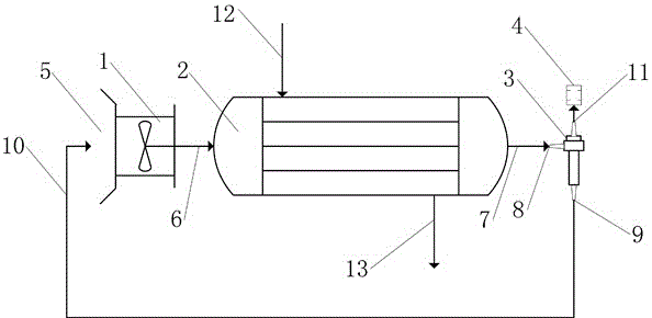
[0017] In this example, refer to figure 1 As shown, an evaporator synergistic anti-frost device includes a closed evaporator 2, a heat medium inlet 12 arranged on one side of the closed evaporator 2, and a heat medium inlet 12 arranged on the other side of the closed evaporator 2. Media outlet 13, and the high-pressure air inlet 6 that is arranged on the left side of the closed evaporator 2, and the high-pressure blower 1 connected with the high-pressure air inlet 6, and the ambient air inlet 5 that is arranged on the left side of the high-pressure blower 1, and is arranged on the closed The high-pressure air outlet 7 on the right side of the type evaporator 2, and the vortex tube inlet 8 connected with the high-pressure air outlet 7, and the vortex tube 3 connected with the vortex tube inlet 8, and the vortex tube cold air outlet arranged on one end of the vortex tube 3 11, and the silencer 4 that is connected with the vortex tube cold air outlet 11, and the vortex tube hot g...


PUM


Abstract

The invention discloses an evaporator effect-enhancing and anti-frosting device, comprising a closed type evaporator, a heating medium inlet, a heating medium outlet, a high-pressure air inlet, a high-pressure draught fan, an environmental air inlet, a high-pressure air outlet, a vortex pipe inlet, a vortex pipe, a cold-air outlet of the vortex pipe, a silencer, a hot-air outlet of the vortex pipe, and a hot-air return pipeline. According to the device, for the working condition of low-temperature heat exchange, the rise of the temperature of pressurized air in the closed type evaporator is realized by using the high-pressure draught fan; as environmental air is subjected to the temperature rise, and then is subjected to heat exchange, so that the heat exchange efficiency is improved, and the frosting or freezing can be prevented; the vortex pipe is adopted for implementing further treatment on high-pressure air flow after the heat exchange; two types of air flow, namely, the high-temperature air flow and low-temperature air flow, are obtained; the high-temperature air flow which still contains the relatively high heat content is reused; with further decrease in the temperature of emitted gas, the heat exchange is relatively thorough and relatively efficient.

Description

technical field [0001] The invention relates to the technical field of evaporators, in particular to an evaporator synergistic anti-frost device and a method for using the same. Background technique [0002] An evaporator is a common device that uses heat exchange to transfer and absorb heat. It is an important part of a heat pump system and is widely used in some household appliances and industrial systems that exchange heat and cold, such as air conditioners and refrigerators. At present, after exchanging heat with the ambient air, the evaporator used as an endothermic heat exchange meets a certain temperature difference and temperature conditions during operation, and some moisture in the air will condense. In autumn and winter, as the ambient temperature drops , the heat exchange efficiency gradually decreases, especially when the ambient temperature is close to or lower than 0°C, frost and ice will also appear. When these frost and ice appear on the surface of the evapo...

Claims


Application Information

Patent Timeline
Patent Type & Authority Patents(China)
IPC IPC(8): F25B47/02
CPCF25B39/02F25B47/00F25B2339/02F25B2347/00F25B41/40
Inventor 苟仲武
Owner 苏州正美光电科技有限公司
Learn More