Non-destructive detection method of pulse-excited infrared thermal wave phase of fixed viewing field

An infrared thermal wave and non-destructive testing technology, applied in the direction of material defect testing, etc., can solve the problems of lack of improvement measures, inconsistent with the actual situation, and restrictions on the application of fine-grained spectrum analysis technology

Inactive Publication Date: 2015-02-18
PLA SECOND ARTILLERY ENGINEERING UNIVERSITY
View PDF3 Cites 46 Cited by
  • Summary
  • Abstract
  • Description
  • Claims
  • Application Information

AI Technical Summary

Problems solved by technology

The above-mentioned existing spectrum refinement methods mainly focus on the refinement of the amplitude spectrum and power spectrum, but there are not many studies on the core phase analysis of the PPT method, especially for the downsampled data length and The refinement multiple grows at the same multiple, and its source can only be filled with 0, which is inconsistent with the actual situation, and there is a lack of effective improvement measures, which seriously limits the application of the refinement spectrum analysis technology
[0006] To sum up, so far, a simple, practical and effective method has not been found, which can precisely process the infrared thermal wave pulse phase image to meet the needs of rapid non-destructive detection and identification of equipment defects

Method used


Image

  • Non-destructive detection method of pulse-excited infrared thermal wave phase of fixed viewing field
  • Non-destructive detection method of pulse-excited infrared thermal wave phase of fixed viewing field
  • Non-destructive detection method of pulse-excited infrared thermal wave phase of fixed viewing field

Examples


Embodiment Construction

[0082] Below in conjunction with accompanying drawing, specific embodiment example of the present invention is described further:

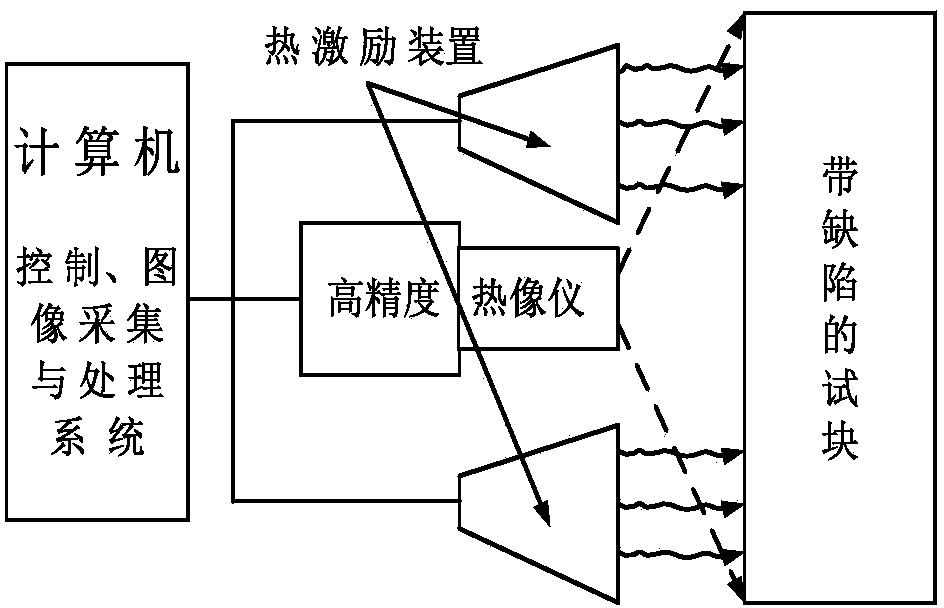
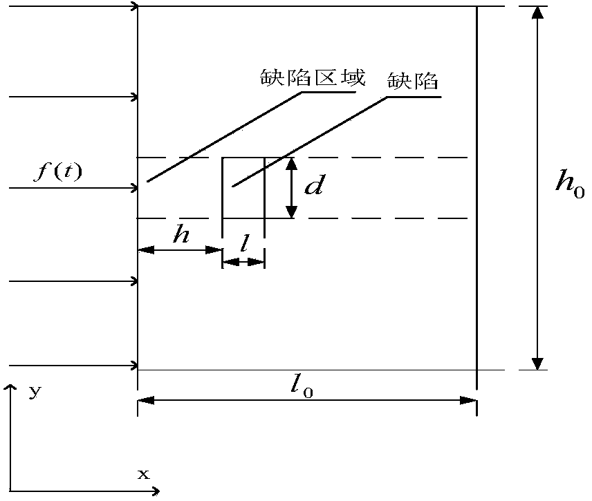
[0083] The implementation method of step 1 is as follows (see figure 1 , 2 , 4, 5, 6):

[0084] (1) The method of obtaining thermal wave images. The detection device of the pulse thermal imaging method is composed of a thermal imager, a computer, a display, a power supply and a thermal excitation source. During the detection process, the thermal excitation source sends a thermal excitation signal to heat the detection object instantaneously or for a short time, and the thermal imager collects the time and space distribution information of the surface temperature field of the measured object to form an infrared thermal wave image sequence. The sequence value is the infrared radiation density of the corresponding point, which can be converted into a temperature value. The thermal image sequence is analyzed by computer fitting, compression, recons...


PUM

PropertyMeasurementUnit
thermal conductivityaaaaaaaaaa
specific heat capacityaaaaaaaaaa
densityaaaaaaaaaa

Abstract

The invention relates to a non-destructive detection method of pulse-excited infrared thermal wave phase of a fixed viewing field. The non-destructive detection method comprises the following steps: comprehensively applying a multiple-modulation Zoom-FFT refining spectrum method, a thermal-wave data fitting extension method and a zero-phase digital filter method, and carrying out high-accuracy spectral analysis on acquired continuous equally-spaced infrared thermal-wave image sequences before and after thermal excitation, thus quickly obtaining precise ultralow-frequency thermal-image phase diagram and amplitude diagram, and further realizing detection and recognition for defects or damages of equipment. Compared with the prior art, the non-destructive detection method has the beneficial effects that not only can the acquisition frequency, the acquisition time, the acquisition frame number and the refining degree of analysis of thermal images be flexibly set, but also the detection speed, the refining degree and the precision degree can be increased by ten times respectively, the multiplied increase of the detection effect and the detection depth of the defects also can be realized, simultaneously the requirement for computer hardware is also reduced, so that the method is flexible in use, is especially suitable for non-destructive detection of the infrared thermal wave on site and has a wide application prospect.

Description

technical field [0001] The invention belongs to the technical field of thermal wave nondestructive detection image processing, and relates to a nondestructive detection method of infrared thermal wave pulse phase with a fixed field of view. Background technique [0002] Thermal Wave non-destructive testing technology is a new type of non-destructive testing technology emerging in the field of aerospace and defense in the United States in the 1990s. Since 1990, many countries at home and abroad have actively carried out the research on thermal wave theory and technology. field has increasingly wide applications. The theoretical basis of thermal wave detection technology is the theory of thermal wave conduction and the law of thermal radiation. The research focuses on the interaction between variable heat sources (such as periodic, pulse, step function heat sources, etc.) and the detected object and its geometric structure. After being heated, the physical structure characte...

Claims


Application Information

Patent Timeline
Patent Type & Authority Applications(China)
IPC IPC(8): G01N25/72
Inventor 张金玉张炜苏勋家杨正伟田干孟祥兵王冬冬陶胜杰宋鸿杰
Owner PLA SECOND ARTILLERY ENGINEERING UNIVERSITY
Why Eureka
Try Eureka