Method for positioning constructed wetland blocked area on basis of two-dimensional resistivity imaging technology

A technology of resistivity imaging and constructed wetlands, applied in electric/magnetic exploration, acoustic re-radiation, geophysical measurement, etc.

Inactive Publication Date: 2015-02-18
GUILIN UNIVERSITY OF TECHNOLOGY
View PDF3 Cites 27 Cited by
  • Summary
  • Abstract
  • Description
  • Claims
  • Application Information

AI Technical Summary

Problems solved by technology

[0007] The purpose of the present invention is to solve the clogging problem in constructed wetlands, and provide

Method used


Image

  • Method for positioning constructed wetland blocked area on basis of two-dimensional resistivity imaging technology
  • Method for positioning constructed wetland blocked area on basis of two-dimensional resistivity imaging technology
  • Method for positioning constructed wetland blocked area on basis of two-dimensional resistivity imaging technology

Examples


Embodiment 1

[0030] Two-dimensional resistivity imaging technology of constructed wetlands without clogging.

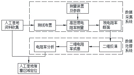
[0031] The process of locating the clogged area of ​​constructed wetland based on two-dimensional resistivity imaging technology is as follows: figure 1 As shown, on the basis of collecting and analyzing the existing data of the constructed wetland, reasonably arrange the measuring line and set the acquisition parameters, and obtain the apparent resistivity section under the measuring line through the high-density resistivity measurement method; then the collected apparent resistivity Perform two-dimensional inversion of the section, convert the apparent resistivity data into resistivity data, and draw the contour map of the resistivity section to realize two-dimensional resistivity imaging; finally, by analyzing the two-dimensional resistivity imaging section, the detection of artificial Purpose of wetland clogged areas.

[0032] The specific steps are:

[0033] (1) Surveying l...

Embodiment 2

[0039] Two-dimensional resistivity imaging of constructed wetlands with clogged regions.

[0040] The detection and analysis process of this embodiment is as follows figure 1 .

[0041] The specific steps are:

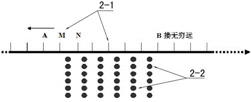
[0042] (1) Surveying line layout: Arrange high-density surveying lines above the constructed wetland with a distance of 50cm between surveying lines and 10cm between measuring points. .

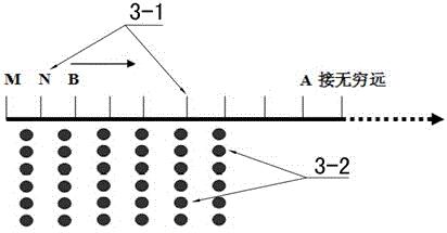
[0043] (2) AMN device measurement: First, arrange the three-pole positive device AMN device (such as figure 2 ), the negative pole B of the power supply is connected to the "infinity" pole, and the electrode arrangement adopts a "rectangular AMN" device; when measuring, M and N in 2-1 do not move, and A moves to the left point by point to obtain a rolling line. Then A, M, and N move one electrode to the right at the same time, M, and N do not move, and A moves to the left point by point again to get another rolling line, so that the rolling measurement continues to get an apparen...


PUM

PropertyMeasurementUnit
Resistivityaaaaaaaaaa

Abstract

The invention discloses a method for positioning a constructed wetland blocked area on the basis of the two-dimensional resistivity imaging technology. The method includes the steps of firstly, conducting a two-dimensional apparent resistivity section survey through the high-intensity resistivity method and three-pole rectangular AMN and MNB devices by reasonably arranging survey lines and setting collection parameters on the premise of the resistivity difference between the blocked packing area and the non-blocked packing area and on the basis of collecting and analyzing existing constructed wetland resources; secondly, conducting two-dimensional inversion on the two three-pole apparent resistivity sections obtained through measurement, converting apparent resistivity data into resistivity data, drawing the contour map of the resistivity sections, and achieving constructed wetland two-dimensional resistivity imaging; thirdly, achieving the aim of positioning the constructed wetland blocked area according to the two-dimensional resistivity imaging characteristics and the resistivity difference analysis. The method is economical and easy to conduct and can fill in the technical gaps in the constructed wetland blocked area two-dimensional positioning, and the powerful technical guarantees are provided for continuous and efficient running of constructed wetlands.

Description

technical field [0001] The invention belongs to the technical field of sewage treatment, and in particular relates to a method for locating clogged areas of constructed wetlands based on two-dimensional resistivity imaging technology. Background technique [0002] Constructed wetland sewage treatment technology is a new ecological engineering technology for sewage treatment that emerged in the 1970s. It has the advantages of good flexibility, low investment, low energy consumption, strong decontamination ability, convenient management, and no secondary pollution. Applications are increasingly common. However, in recent years, problems such as clogging frequently occur in constructed wetlands during operation, the purification performance decreases, and the service life is shortened. For example, among the 355 subsurface flow constructed wetlands in the United States and the United Kingdom, nearly half of them were blocked within five years of use, and the hydraulic conducti...

Claims


Application Information

Patent Timeline
IPC IPC(8): G01V3/04G01N27/04
Inventor 丁彦礼解庆林白少元孙琳
Owner GUILIN UNIVERSITY OF TECHNOLOGY
Why Eureka
Try Eureka