

Image capture device and image capture method
A camera device and the technology of the camera department, applied in the field of medical cameras, can solve problems such as difficult operation and risks
- Summary
- Abstract
- Description
- Claims
- Application Information
AI Technical Summary
Problems solved by technology
Method used
Image

Examples
Embodiment approach 1
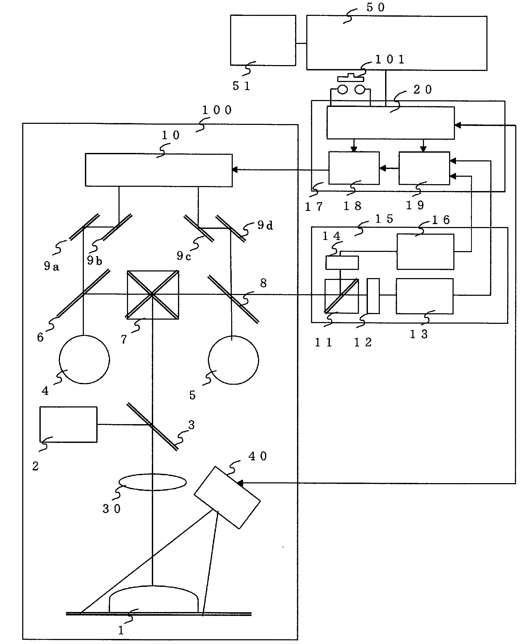
[0026] figure 1 It is an overall block diagram of the imaging device according to Embodiment 1 of the present invention. also, figure 2 is a concrete representation of the imaging device according to Embodiment 1 of the present invention figure 1 Block diagram of the illumination structure.
[0027] First, refer to the following image 3 Description of the characteristics figure 1 , figure 2 . exist figure 1 In the microscope case 100, a three-dimensional measurement light source 40 for illuminating the subject 1, a normal light source 2, an objective lens 30, and an illumination dichroic mirror 3 are provided below the main dichroic mirror 7.
[0028] In addition, in normal naked eye observation, the optical image of the subject 1 obtained by epi-illumination from the normal light source 2 passes through the left dichroic mirror 6 for the naked eye and the dichroic mirror 8 for the right naked eye in the eyepiece part 4 for the left and the dichroic mirror for the ri...
Embodiment approach 2
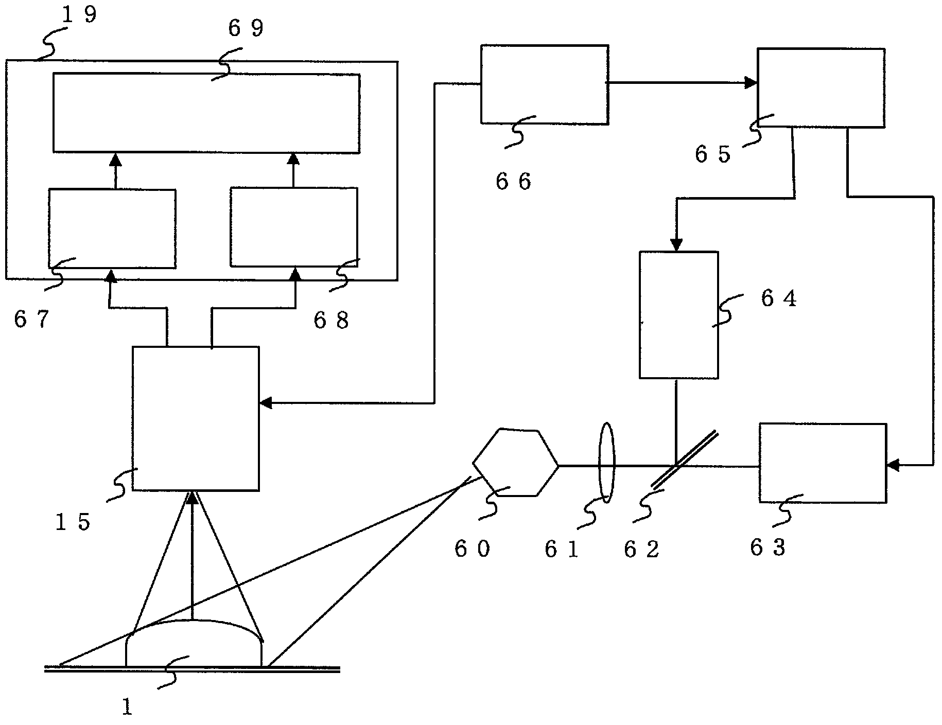
[0061] Figure 9 It is an overall block diagram of the imaging device according to Embodiment 2 of the present invention. also, Figure 10 is a concrete representation of the imaging device according to Embodiment 2 of the present invention Figure 9 Block diagram of the illumination structure.
[0062] First, refer to the aforementioned image 3 Description of the characteristics Figure 9 and Figure 10 . exist Figure 9 In the microscope case 100 , a three-dimensional measurement light source 55 for illuminating the subject 1 , an objective lens 30 , and an illumination dichroic mirror 3 are provided below the main dichroic mirror 7 . In addition, the light source 55 for three-dimensional measurement is also used for normal naked eye observation.
[0063] The light source 55 for three-dimensional measurement in the normal observation mode operates as epi-illumination in a wavelength band of visible light of about 300 to 700 nm. The light source illuminates the subj...
Embodiment approach 3
[0091] Figure 12 It is an overall block diagram of the imaging device according to Embodiment 3 of the present invention. First, refer to the aforementioned image 3 Description of the characteristics Figure 12 . exist Figure 12 In the microscope case 100, a three-dimensional measurement light source 40 for illuminating the subject 1, a normal light source 80 including excitation light, an objective lens 30, and an illumination dichroic mirror 3 are provided below the main dichroic mirror 7. .
[0092] In addition, in normal naked eye observation, the optical image of the subject 1 obtained by epi-illumination from a normal light source 80 including excitation light is viewed on the left through the dichroic mirror 6 for the left naked eye and the dichroic mirror 8 for the right naked eye. An image is formed in the eyepiece part 4 and the right eyepiece part 5 . On the other hand, the imaging optical axis is reflected by the main dichroic mirror 7 and split by the ima...
PUM
 Abstract
Description
Claims
Application Information