
Thermosiphon systems for electronic devices

A siphon system and evaporator technology, applied in the direction of electric solid devices, electrical components, semiconductor devices, etc., can solve the problems of speed, efficiency and cost, forced convection is not very effective, and difficult to cool areas, etc., to achieve improvement Effect of heat transfer, reduction of manufacturing cost, enhancement of thermal characteristics

Active Publication Date: 2015-02-18
GOOGLE LLC
View PDF7 Cites 1 Cited by
  • Summary
  • Abstract
  • Description
  • Claims
  • Application Information

AI Technical Summary

Problems solved by technology

In some cases, one or more components or devices on a server tray may be located in areas of the tray that are difficult to cool; for example, areas where forced convection is less effective or unavailable
[0004] The result of inadequate and / or insufficient cooling may be the failure of one or more electronic components on the tray due to the temperature of the component exceeding the maximum rated temperature
While some redundancy may be built into computer data centers, server racks, or even individual trays, component failure due to overheating can still have significant costs in speed, efficiency, and expense

Method used


Image

  • Thermosiphon systems for electronic devices
  • Thermosiphon systems for electronic devices
  • Thermosiphon systems for electronic devices

Examples


Embodiment Construction

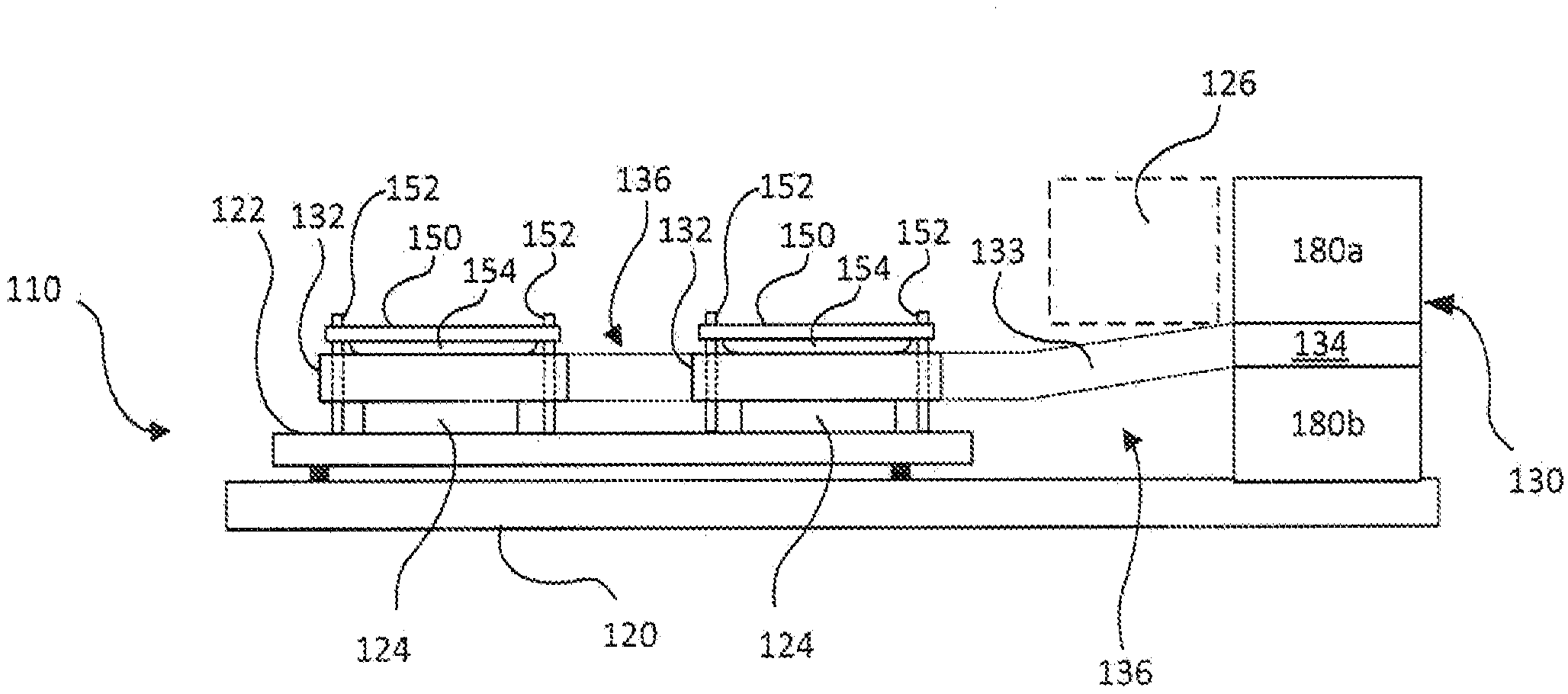
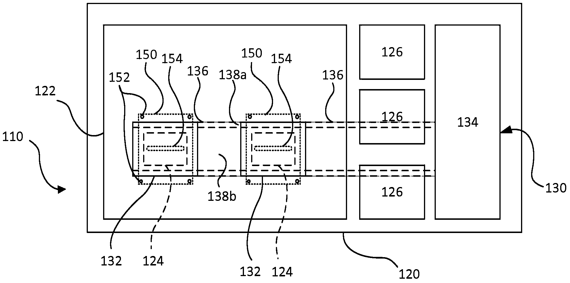
[0039] This document discusses a thermosyphon system that can be implemented to remove heat from an electronic device, such as a component of a computing device, such as a processor or memory. The evaporator of the thermosiphon system contacts the electronic device such that the electronic device experiences a conductive heat transfer effect. Therefore, the thermosiphon system can be used as a heat sink for electronic devices, reducing the possibility of electronic devices overheating and thus malfunctioning.

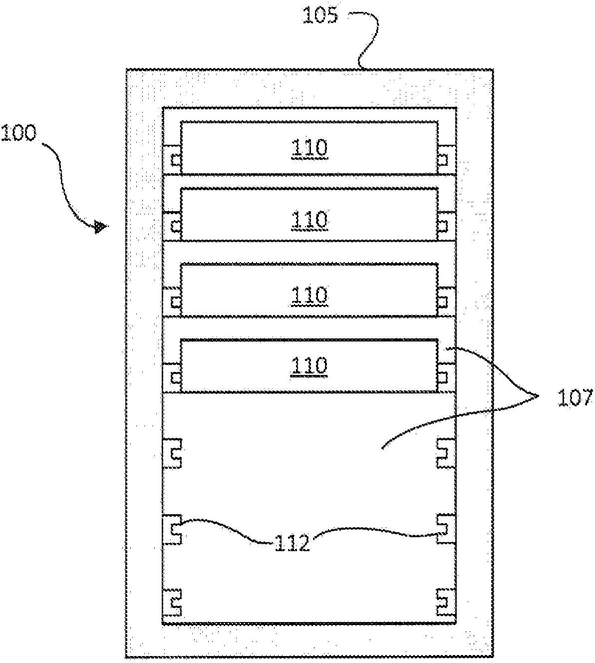
[0040] In particular, the thermosyphon system may be mounted on or integrated with a server rack subassembly for ease of insertion into a server rack. A server rack subassembly may contain or support a number of heat generating electronics, and the evaporator of the thermosiphon system may contact one or more of these electronics. Additionally, the thermosiphon system may be mounted on circuit card assemblies, daughter cards, and / or other boards carrying heat generatin...


PUM


Abstract

A thermosiphon system includes a condenser, an evaporator, and a condensate line fluidically coupling the condenser to the evaporator. The condensate line can be a tube with parallel passages can be used to carry the liquid condensate from the condenser to the evaporator and to carry the vapor from the evaporator to the condenser. The evaporator can be integrated into the tube. The condenser can be constructed with an angled core. The entire assembly can be constructed using a single material, e.g., aluminum, and can be brazed together in a single brazing operation.

Description

technical field [0001] The present invention relates to thermosiphon systems for removing heat from electronic devices. Background technique [0002] Computer users are often concerned with the speed (eg, megahertz and gigahertz) of the computer's microprocessor. Many people forget that this speed often comes with a cost—higher power consumption. This power dissipation also generates heat. This is because by simple laws of physics, all power has to go somewhere, and that somewhere is ultimately converted to heat. A pair of microprocessors mounted on a single motherboard can draw several hundred watts or more. For the many computers in a large data center, this number needs to be multiplied by the thousands (or tens of thousands) to easily understand the amount of heat that can be generated. The impact of power consumed by critical loads in a data center is often exacerbated when incorporating all the auxiliary equipment required to support the critical loads. [0003] E...

Claims


Application Information

Patent Timeline
Patent Type & Authority Applications(China)
IPC IPC(8): G06F1/20H05K7/20
CPCF28D15/0275H01L2924/0002F28F2013/006H01L23/367H01L23/4006F28D15/0266H01L2023/4087H05K7/20809H01L2023/4081Y10T29/49393H01L23/427F28F1/40H01L2924/00H01L23/3675B23P15/26
Inventor 杰里米·赖斯杰弗里·S·斯伯丁胡安·D·恩古彦
Owner GOOGLE LLC
Learn More