Incinerator flue gas purification system

A flue gas purification system and incinerator technology, applied in chemical instruments and methods, dispersed particle separation, combined devices, etc., can solve problems such as low processing efficiency, inappropriateness, and reduced dust filtration efficiency, and achieve the goal of improving slag discharge efficiency Effect

Inactive Publication Date: 2016-03-23
HEFEI HUANKUN SLUDGE DRYING EQUIP
View PDF7 Cites 0 Cited by
  • Summary
  • Abstract
  • Description
  • Claims
  • Application Information

AI Technical Summary

Problems solved by technology

Even if it is a small amount of flue gas extracted after precipitation, its own humidity and the lime slurry trapped in it will spread a large amount of paste on the dust bag surface of the bag filter along with the progress of the flue gas, resulting in its The filter holes on the bag surface are completely blocked by lime slurry, which greatly reduces its actual dust filtration efficiency
Finally, even a small amount of filtered gas after passing through the bag filter is still difficult to meet the current stringent emission requirements, and it is often necessary to add other removers such as charcoal to achieve further processing purposes
But the reality is that all additives have their own optimal reaction temperature, and the current additives are added directly after the above-mentioned reaction, completely ignoring the requirements of various aspects such as reaction temperature, resulting in "inappropriate temperature It is not uncommon to have an inappropriate reaction, which is an important reason for its low processing efficiency

Method used


Image

  • Incinerator flue gas purification system
  • Incinerator flue gas purification system
  • Incinerator flue gas purification system

Examples


Embodiment Construction

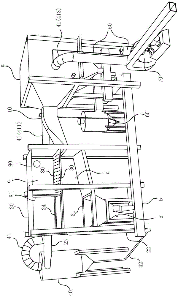
[0039] For ease of understanding, combined here Figure 1-4 Specifically set forth the component structure of the present invention and its specific work flow:

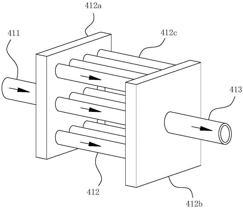
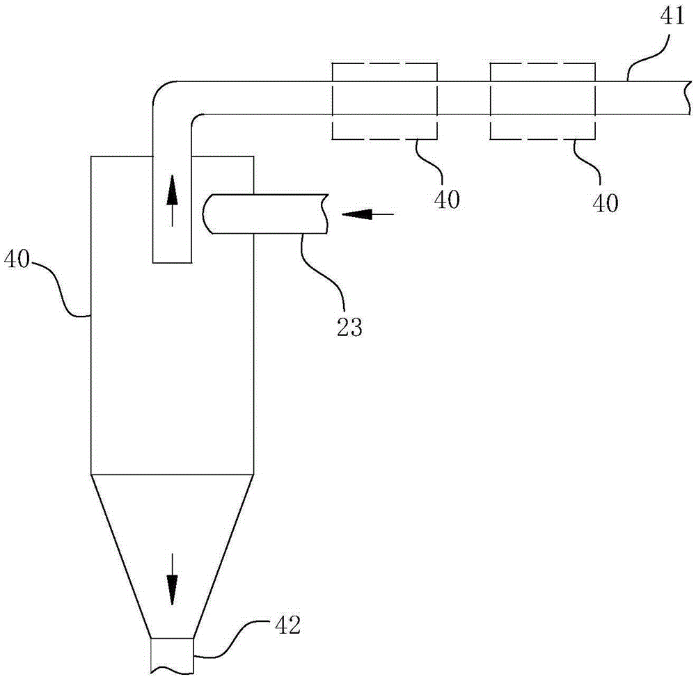
[0040] The specific implementation structure of the present invention is as Figure 1-3 As shown, it includes a processing chamber 20 , a cyclone separator 40 and a draft blower 70 sequentially arranged along the working path of the system. Among them, the treatment chamber 20 communicates with the tail end of the flue a through the flue gas outlet pipe 10, the ash outlet of the lime distributor 60 is arranged at the lumen of the flue gas outlet pipe 10, and the cyclone separator 40 and the treatment chamber 20 are connected by a steam outlet pipe The road 23 communicates, and the air outlet pipe 41 communicates between the drainage fan 70 and the cyclone separator 40 . In order to ensure the water vapor separation efficiency, multiple water vapor separation components of the same type or different types can be arra...


PUM


Abstract

The invention belongs to the field of waste incineration equipment and particularly relates to a flue-gas purifying system of an incineration furnace applicable to treating flue gas from incineration of the incineration furnace. The flue-gas purifying system at least comprises a flue-gas leading-out pipe and a treating chamber, wherein a water curtain part is arranged at the treating chamber, and the water discharging direction of the water curtain part is vertical to or intersected with the moving direction of the flue gas at the outlet of the flue-gas leading-out pipe; a precipitate deslagging port is arranged at the bottom part of the treating chamber; the treating chamber is internally provided with a communicating pipe for communicating with an external inner-circulation reservoir and a steam discharging pipeline; a gas discharging pipe of a water-steam separating component extends towards the tail end of a flue and penetrates into an inner cavity of the flue; and a water discharging pipe of the water-steam separating component is communicated with the external inner-circulation reservoir. The flue-gas purifying system also comprises a carbon-powder distributor and a lime distributor. The flue-gas purifying system can provide a basic hardware platform for treating the flue gas of the current high-efficiency incineration furnace, is high in flue-gas treating efficiency and good in working reliability, and can be well qualified for the need of high-efficiency, harmless and rapid treatment of the flue gas from incineration of various current incineration furnaces.

Description

technical field [0001] The invention belongs to the field of waste incineration equipment, and in particular relates to an incinerator flue gas purification system suitable for treating incinerator flue gas. Background technique [0002] Garbage incineration is the most effective way to achieve harmless, volume reduction, and resourceful treatment of garbage. Waste incineration technology is very mature in developed countries and has accumulated more than 20 years of experience. But for our country, it is a new field to be developed and studied. Although my country has made a lot of progress in waste incineration, it is still in the stage of exploration and research. As early as a few years ago, my country's waste incinerator tail gas emission limit regulations ("Standards for Pollution Control of Domestic Waste Incineration" (GB18485-2001)) have been announced, and it is even more stringent for the exhaust gas emission requirements of incinerators. the point. [0003] At...

Claims


Application Information

Patent Timeline
Patent Type & Authority Patents(China)
IPC IPC(8): B01D53/75B01D50/00
Inventor 李登平韩莹
Owner HEFEI HUANKUN SLUDGE DRYING EQUIP
Why Eureka
Try Eureka