
Heavy duty double-shaft scrap steel shredder

A shredder and heavy-duty technology, which is applied in the field of heavy-duty double-shaft scrap shredders, can solve problems such as irregular operations, explosions, and waste of manpower, and achieve the effects of strong shredding capacity, low speed, and high torque

Inactive Publication Date: 2015-02-25
GUANGZHOU 3E MACHINERY
View PDF7 Cites 7 Cited by
  • Summary
  • Abstract
  • Description
  • Claims
  • Application Information

AI Technical Summary

Problems solved by technology

[0003] At present, the processing methods for ordinary (10mm) scrap steel include shearing, manual baler or manual briquetting, and then binding and returning to the furnace. However, 10-20mm scrap steel, especially the larger scrap It is necessary to use high-pressure acetylene equipment or manual acetylene equipment for cutting. During the cutting process, not only will a large amount of cutting waste residue be generated, a large amount of acetylene resources will be wasted, but also a large amount of carbon dioxide and other gases will be released, causing great pollution to the environment. This treatment method The technical means are backward, and the operation is not standardized, which is easy to cause explosion, endangering people's life and property safety, causing waste of manpower and increase of cost

Method used


Image

  • Heavy duty double-shaft scrap steel shredder
  • Heavy duty double-shaft scrap steel shredder
  • Heavy duty double-shaft scrap steel shredder

Examples


Embodiment Construction

[0034] The principles and features of the present invention are described below in conjunction with the accompanying drawings, and the examples given are only used to explain the present invention, and are not intended to limit the scope of the present invention.

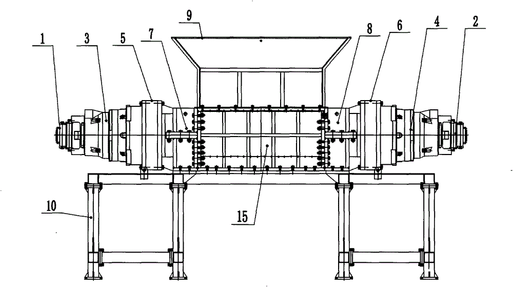
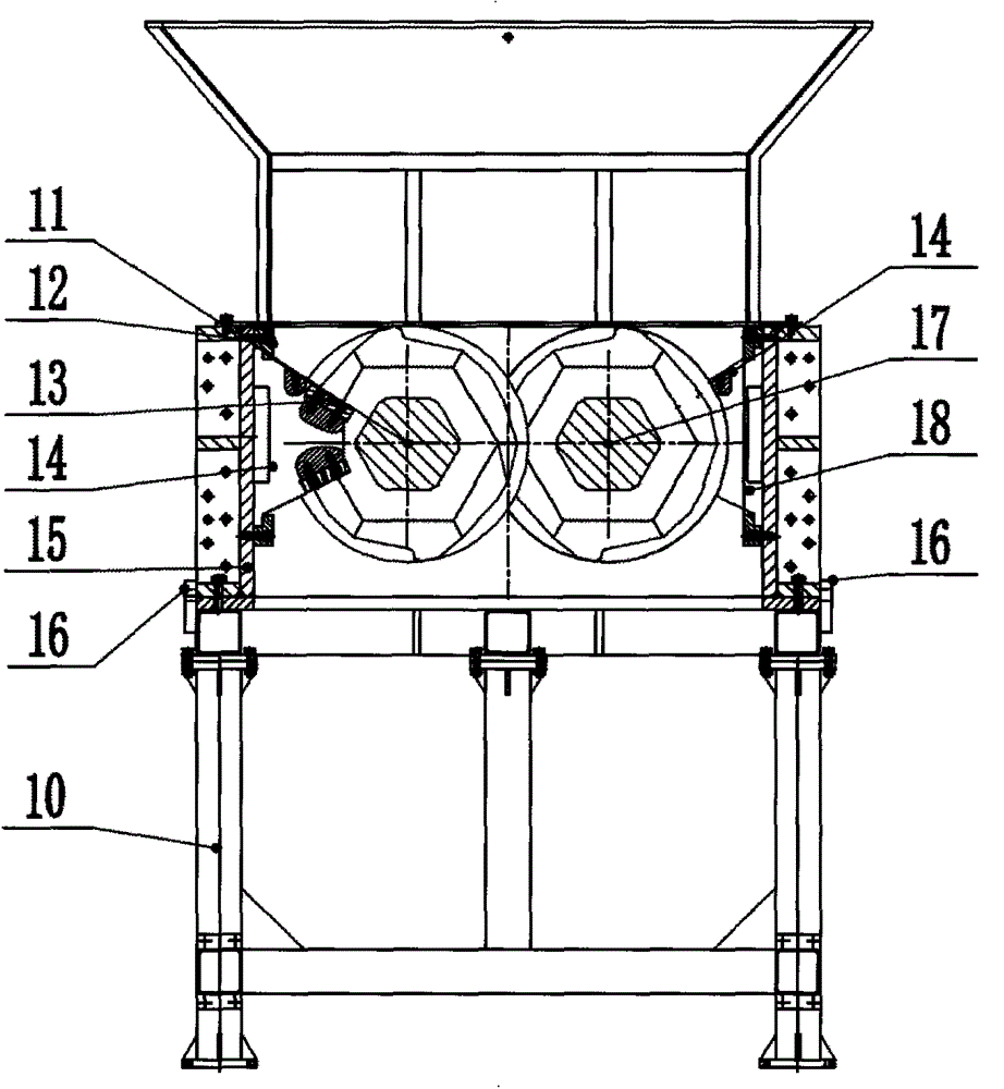
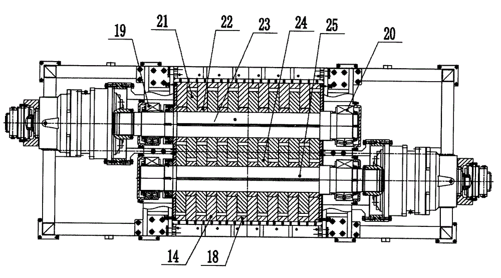
[0035] A heavy-duty twin-shaft scrap shredder, such as figure 1 , figure 2 , image 3 and Figure 4 As shown, it includes frame 10, box body 15, feed hopper 9, left and right hydraulic motors 1, 2, left and right reducers 3, 4, left and right connecting flanges 5, 6, front and rear knife rollers 17, 11 and installation of front and rear knife rollers The left and right bearing blocks 7, 8, 19, 20 of 17, 11, the box 15 is installed on the frame 10, the top of the box 15 is provided with an opening, and the feeding hopper 9 is installed in the box On the top opening of body 15, the left and right bearing seats 7, 8 of the front knife roller and the left and right bearing seats 19, 20 of the rear knife roller are r...


PUM


Abstract

The present invention relates to a heavy duty double-shaft scrap steel shredder, which comprises a frame, a box, a material inlet hopper, a left hydraulic motor, a right hydraulic motor, a left speed reducer, a right speed reducer, a left connection flange, a right connection flange, a front cutter roller, a rear cutter roller, left bearing pedestals for arranging the front cutting roller and the right cutting roller, and right bearing pedestals for arranging the front cutting roller and the right cutting roller, wherein the box is arranged on the frame, the top portion of the box is provided with an opening, the material inlet hopper is arranged on the box opening on the top portion, the left side and the right side of the box are respectively provided with the front cutting roller left bearing pedestal, the front cutting roller right bearing pedestal, the rear cutting roller left bearing pedestal and the rear cutting roller right bearing pedestal, the front cutting roller right bearing pedestal is connected with the right flange, the rear cutting roller left bearing pedestal is connected with the left flange, the left speed reducer and the right speed reducer are respectively connected with the left hydraulic motor and the right hydraulic motor, the front cutter roller is arranged on the front cutting roller left bearing pedestal and the front cutting roller right bearing pedestal, the front cutter roller and the rear cutter roller are connected on the left speed reducer and the right speed reducer, and the front cutter roller and the rear cutter roller are provided with a front shaft cutter for shredding the material and a rear shaft cutter for shredding the material. The heavy duty double-shaft scrap steel shredder has advantages of low rotation speed, low noise, high torque, strong medium-thick steel plate shredding ability, low energy consumption, safety, reliability and the like, and can used for batch and mechanized scrap steel material treatment.

Description

technical field [0001] The invention relates to a steel plate shredder with a thickness of less than 20 mm, in particular to a heavy-duty double-shaft scrap steel shredder. Background technique [0002] With the rapid development of industry, the use and demand of steel plates, especially medium and extra-thick steel plates, are increasing. However, the corners and scraps of steel plates are also gradually increasing with the continuous increase in production and use. [0003] At present, the processing methods for ordinary (10mm) scrap steel include shearing, manual baler or manual briquetting, and then binding and returning to the furnace. However, 10-20mm scrap steel, especially the larger scrap It is necessary to use high-pressure acetylene equipment or manual acetylene equipment for cutting. During the cutting process, not only will a large amount of cutting waste residue be generated, a large amount of acetylene resources will be wasted, but also a large amount of carb...

Claims


Application Information

Patent Timeline
IPC IPC(8): B02C4/02B02C4/28B02C4/30B02C4/42
CPCB02C4/02B02C4/28B02C4/30B02C4/42
Inventor 张雷
Owner GUANGZHOU 3E MACHINERY
Learn More