Blade structure formed in one time and machining method

A blade and blade technology, applied in the field of blade teeth and blade structure, can solve problems such as affecting blade strength, blade breakage, short service life, etc., and achieve the effects of high cutting efficiency, increased sharpness, and long service life.

Active Publication Date: 2015-02-25
XIAMEN LAIRY ELECTRIC APPLIANCES
View PDF5 Cites 2 Cited by
  • Summary
  • Abstract
  • Description
  • Claims
  • Application Information

AI Technical Summary

Problems solved by technology

Such a knife tooth 20 forms a cutting angle β on both sides between the two side surfaces and the bottom surface. The cutting angle β is generally between 60-80 degrees, and the cutting effect is not ideal.
[0003] If the cutting angle β on both sides of the blade 20 is specially reduced in order to improve the cutting effect, the oblique triangular prism 30 will also be more inclined, causing the blade base 10 to be too thin near the blade 20, which will affect the strength of the entire blade and cause the blade Easy to break, short service life

Method used


Image

  • Blade structure formed in one time and machining method
  • Blade structure formed in one time and machining method
  • Blade structure formed in one time and machining method

Examples


Embodiment Construction

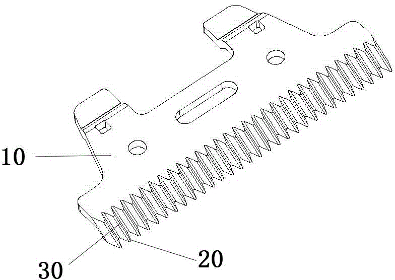
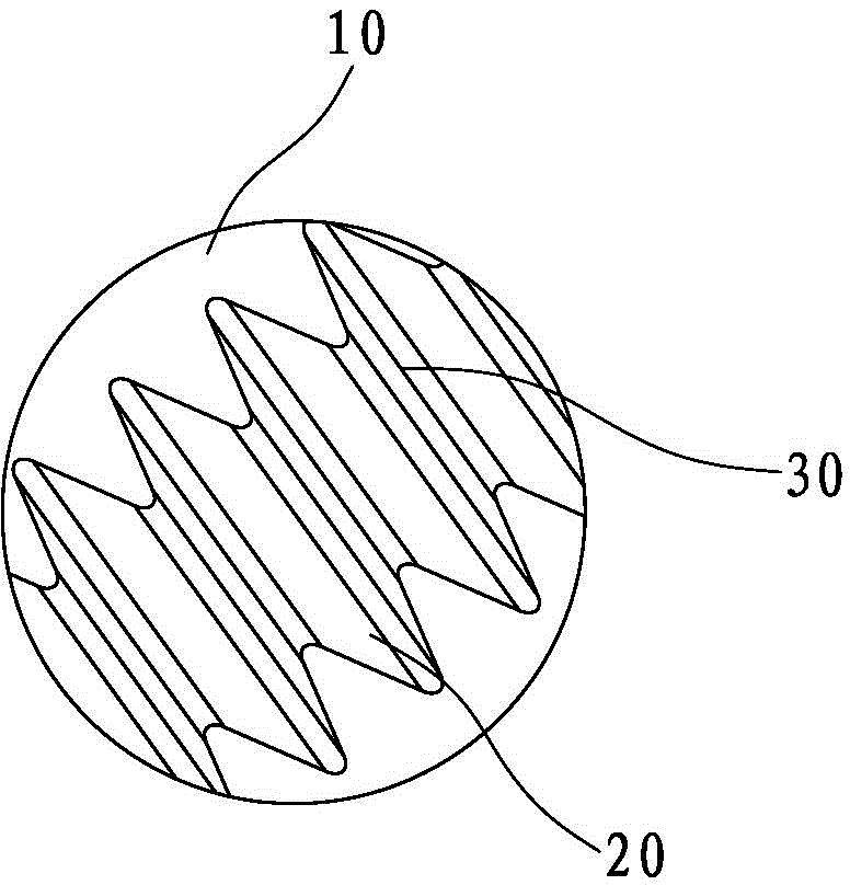
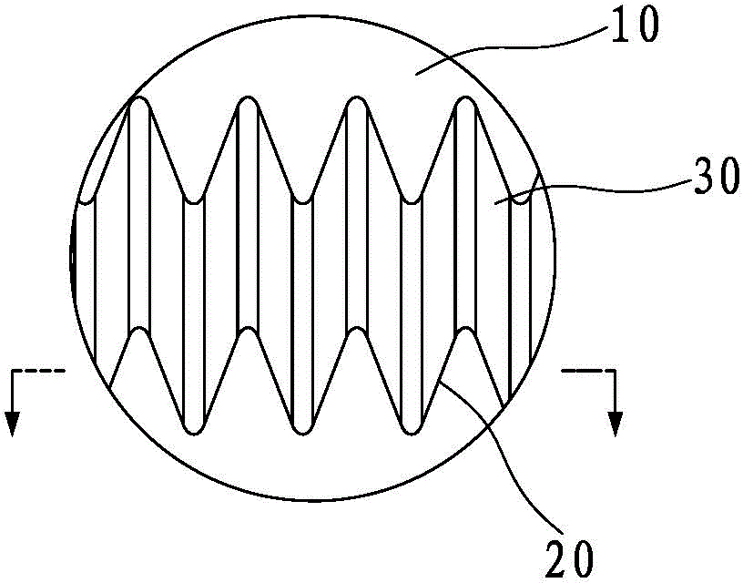
[0040] Such as Figure 2-1 to Figure 6-3 As shown, the one-shot blade structure disclosed by the present invention is composed of a blade base body 1 and a knife tooth 2. The front portion of the blade base body 1 directly forms a triangular cone 3, and a conical surface 31 of the triangular cone 3 is connected to the blade base body. The front portion of 1 is connected, and the bottom surface 32 of triangular pyramid 3 and other two conical surfaces 33,34 form cutter tooth 2, form the cutting angle γ of cutter tooth 2 both sides between two conical surfaces 33,34 and bottom surface 32.

[0041] Under the premise of ensuring the strength of the knife tooth 2, the present invention can reduce the cutting angle γ on both sides of the knife tooth 2 as much as possible, and the cutting angle γ can be between 30-65 degrees, which increases the sharpness of the knife tooth 2 and makes the cutting efficiency more efficient. Moreover, this structure does not change the thickness of th...


PUM

PropertyMeasurementUnit
Cut corneraaaaaaaaaa

Abstract

The invention discloses a blade structure formed in one time. The blade structure formed in one time consists of a blade base body and blade teeth, wherein the front portion of the blade base body directly forms a triangular cone, one conical face of the triangular cone is connected with the front portion of the blade base body, the bottom face of the triangular cone and the other two conical faces form the blade teeth, and corner cuts on two sides of the blade teeth are formed between the two conical faces and the bottom face. A machining method comprises the steps of adopting a ceramic material, a powder metallurgy material or a precise casting material and the like to form the blade structure by means of a die. On the premise that the strength of the blade teeth is ensured, the corner cuts on the two sides of the blade teeth are decreased as far as possible, the sharpness of the blade teeth is improved, and the cutting efficiency is higher. In addition, the thickness of the blade base body of the blade structure is not changed, the strength of the whole blade is not influenced, and the service life of the blade is long.

Description

technical field [0001] The invention relates to a cutter tooth and blade structure of a blade, in particular to a one-time forming blade structure and processing method, and is suitable for electric hair clippers, temple blades or side blades of electric razors, women's razors and Fixed and moving knives for animal shaver and other products. Background technique [0002] In the prior art, ceramic blades are usually molded with the help of ceramic materials, and their structure is as follows: figure 1 , Picture 1-1 , Figure 1-2 with Figure 1-3 As shown, it is composed of a blade base body 10 and a blade tooth 20 , the blade base body 10 near the blade teeth 20 forms an oblique triangular prism 30 , and the bottom surface and two side surfaces of the oblique triangular prism 30 directly form the blade teeth 20 . Such cutter teeth 20 form a cutting angle β on both sides between the two side surfaces and the bottom surface. The cutting angle β is generally between 60-80 d...

Claims


Application Information

Patent Timeline
IPC IPC(8): B26B19/00
Inventor 刘莱生
Owner XIAMEN LAIRY ELECTRIC APPLIANCES
Why Eureka
Try Eureka