

Thermal transfer device and transfer method for end face of light guide plate
A technology of light guide plate and thermal transfer printing, which is applied in printing devices, transfer printing, rotary printing machines, etc., can solve the problems of inconvenient production, poor quality of micro-structural units and micro-structural units, and achieve simple structure and ensure thermal transfer printing effect , the effect of convenient operation
- Summary
- Abstract
- Description
- Claims
- Application Information
AI Technical Summary
Problems solved by technology
Method used
Image

Examples
Embodiment 1
[0031] The heat transfer microstructure unit on the end face of the light guide plate includes the following steps:
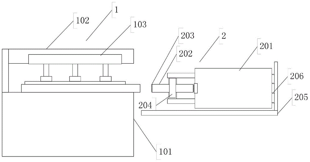
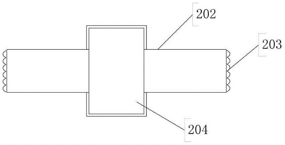
[0032] 1) The light guide plate is fixed on the light guide plate platform 101 by the clamp 103, the light guide plate extends out of the light guide plate platform by 1010.3mm, and the microstructure unit 203 is evenly pasted on the surface of the thermal transfer wheel 202;
[0033] 2) Preheating the thermal transfer wheel 202 by using the heating element 204, the preheating temperature is 70°C;
[0034] 3) Adjust the clamping structure 1 and the thermal transfer structure 2 to an appropriate distance through the bottom surface of the positioning box 201 and the slide rail of the thermal transfer platform 205, so that the thermal transfer wheel 202 fits on the end surface of the light guide plate and extends along the end surface of the light guide plate The light guide plate with the microstructure unit transferred on the end face is obtained.
Embodiment 2
[0036] The heat transfer microstructure unit on the end face of the light guide plate includes the following steps:
[0037] 1) The light guide plate is fixed on the light guide plate platform 101 through the clamp 103, the light guide plate extends out of the light guide plate platform by 1012.0 mm, and the microstructure unit 203 is evenly pasted on the surface of the thermal transfer wheel 202;
[0038] 2) Preheating the thermal transfer wheel 202 with the heating element 204, the preheating temperature is 170°C;
[0039] 3) Adjust the clamping structure 1 and the thermal transfer structure 2 to an appropriate distance through the bottom surface of the positioning box 201 and the slide rail of the thermal transfer platform 205, so that the thermal transfer wheel 202 fits on the end surface of the light guide plate and extends along the end surface of the light guide plate The light guide plate with the microstructure unit transferred on the end face is obtained.
Embodiment 3
[0041] The heat transfer microstructure unit on the end face of the light guide plate includes the following steps:
[0042] 1) The light guide plate is fixed on the light guide plate platform 101 by the clamp 103, the light guide plate extends out of the light guide plate platform by 1010.6mm, and the microstructure unit 203 is evenly pasted on the surface of the thermal transfer wheel 202;
[0043] 2) Preheating the thermal transfer wheel 202 with the heating element 204, the preheating temperature is 80°C;
[0044] 3) Adjust the clamping structure 1 and the thermal transfer structure 2 to an appropriate distance through the bottom surface of the positioning box 201 and the slide rail of the thermal transfer platform 205, so that the thermal transfer wheel 202 fits on the end surface of the light guide plate and extends along the end surface of the light guide plate The light guide plate with the microstructure unit transferred on the end face is obtained.
[0045] After te...
PUM
 Abstract
Description
Claims
Application Information