Bead row and bead feeding device for bead embroidery device

A bead embroidering and bead row technology, which is applied in the direction of auxiliary devices, embroidery machines, embroidery machine mechanisms, etc., can solve the problems of short life, short maintenance period, and movement of bead pipes, and achieve high work efficiency, simple structure, Ease of use

Active Publication Date: 2016-05-25
WENZHOU OULUOHUA INDAL
View PDF6 Cites 3 Cited by
  • Summary
  • Abstract
  • Description
  • Claims
  • Application Information

AI Technical Summary

Problems solved by technology

The above-mentioned design plan uses the time-sharing clamping mechanism, the embroidered bead separation mechanism and the automatic feeding mechanism to make the embroidered beads be sent to the processing station one by one to realize the automatic feeding of the embroidered beads. The installation and maintenance are convenient, the processing cost is low, and it has high practical value, but the service life is not long and the maintenance cycle is short. At the same time, the following adverse consequences will occur when the gripper is separated at different times:
[0004] 1. It will cause the bead tube to move up and down slightly. After a long time of use, the bead tube moves up and down a large distance, and it is necessary to stop the machine to calibrate the position of the bead tube;
[0005] 2. When the clamper separates and separates, it will cause the bead tube to shake and swing, making the bead tube unstable, so that the moving position of the embroidered beads will change, making the embroidered beads unable to be transported normally

Method used


Image

  • Bead row and bead feeding device for bead embroidery device
  • Bead row and bead feeding device for bead embroidery device
  • Bead row and bead feeding device for bead embroidery device

Examples


Embodiment Construction

[0034] The embodiments of the present invention will be described in detail below with reference to the accompanying drawings, but the present invention can be implemented in many different ways defined and covered by the claims.

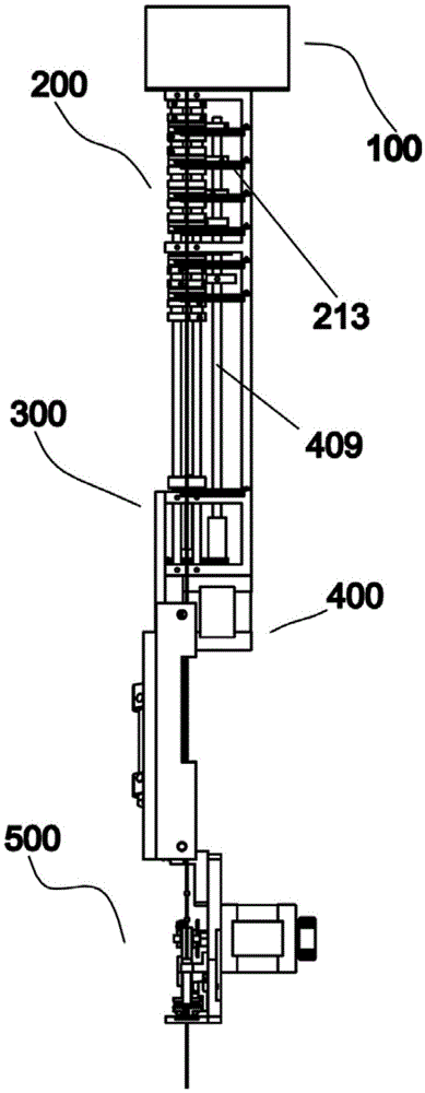
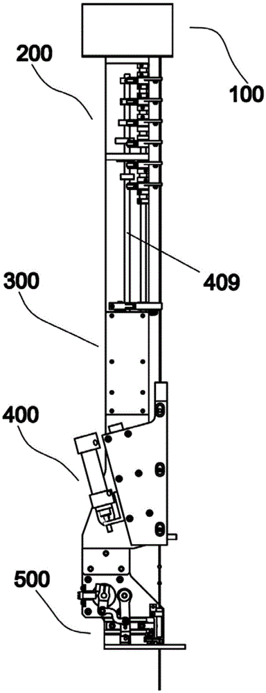
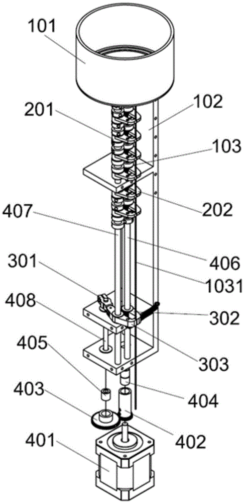
[0035] refer to Figure 1 to Figure 7 ,Such as figure 1Shown is a bead row and bead feeding device for a bead embroidery device, wherein the bead row and bead feeding device includes a bead row mechanism 100, a bead feeding upper section 200, a bead feeding lower section 300, a power drive distribution device 400 and a frame 102. The bead mechanism 100 is set on the upper part of the frame 102, the power drive distribution device 400 is set on the lower part of the frame 102, the upper bead feeding section 200 is located under the bead row mechanism 100, the lower bead feeding section 300 is located between the bead feeding upper section 200 and the power drive distribution device between 400, such as figure 2 As shown, the machine head 500 is al...


PUM


Abstract

The invention discloses a bead arranging and feeding device of a bead embroidery device. The bead arranging and feeding device comprises a rack, a power driving and distributing device which is fixedly arranged on the rack, a bead guide rod for guiding beads to drop and provided with a bead containing section, an upper bead feeding section movably arranged on the rack, and a lower bead feeding section movably arranged on the rack, wherein a bead arranging device is arranged at the upper part of the rack, the upper bead feeding section comprises a plurality of upper section clamping devices, the power driving an distributing device drives at least one upper section clamping device which is used for clamping the bead guide rod; and the lower bead feeding section comprises a lower section clamping device, the power driving and distributing device drives the lower section clamping device to clamp the bead guide rod, and the lower section clamping device is away from the closest upper section clamping device by a distance, so that the enough beads can penetrate the bead containing section between the lower section clamping device and the closest upper section clamping device. The bead arranging and feeding device has a simple structure, can be used conveniently, has the high production efficiency and can clamp the bead guide rod stably.

Description

technical field [0001] The invention relates to a bead embroidery device, in particular to a bead row and bead feeding device for the bead embroidery device. Background technique [0002] In today's social trends, in order to attract consumers to buy more and more clothes, small embroidered beads are sewn onto the clothes as decorative patterns, and these beads are often small in size, which leads to artificial beading in the sewing process. Will greatly reduce production efficiency. [0003] A bead feeding device disclosed in Chinese patent CN201310163593.9 includes a bead guide tube for guiding the drop of bead embroidery, and also includes a time-sharing clamping mechanism, a bead separation mechanism, a feeding mechanism and an automatic feeding mechanism. The hourly clamping mechanism includes several clampers. Driven by the clamping motor, the one-way sleeve drives the mutually spaced clampers to separate and separate in time, so that the bead tube is always in a fixe...

Claims


Application Information

Patent Timeline
Patent Type & Authority Patents(China)
IPC IPC(8): D05C7/08
CPCD05C7/08D05C13/00
Inventor 戴洋德樊小进
Owner WENZHOU OULUOHUA INDAL
Why Eureka
Try Eureka