
Dimming mechanism for automotive lamp self-adaptive high beam lighting system and dimming method thereof

An adaptive high beam and lighting system technology, which is applied in the direction of headlights, lighting devices, lighting and heating equipment, etc., can solve the problem of unstable structure of the self-adaptive dimming mechanism of car lighting, difficult lighting shape control, and spatial structure. Insufficient compactness and other problems, to achieve the effect of light weight, precise control and compact structure

Inactive Publication Date: 2015-02-25
HASCO VISION TECHNOLOGY CO LTD
View PDF7 Cites 15 Cited by
  • Summary
  • Abstract
  • Description
  • Claims
  • Application Information

AI Technical Summary

Problems solved by technology

[0013] As a result, the structure of the adaptive dimming mechanism for the above-mentioned car lamp lighting is unstable, and it is difficult to control the lighting light shape accurately, and because the motor is used to adjust the position of the overall light shape of the far and near beams, its adjustment is not convenient. The adjusted parts are heavy and bulky, and the space structure is not compact enough

Method used


Image

  • Dimming mechanism for automotive lamp self-adaptive high beam lighting system and dimming method thereof
  • Dimming mechanism for automotive lamp self-adaptive high beam lighting system and dimming method thereof
  • Dimming mechanism for automotive lamp self-adaptive high beam lighting system and dimming method thereof

Examples


Embodiment 1

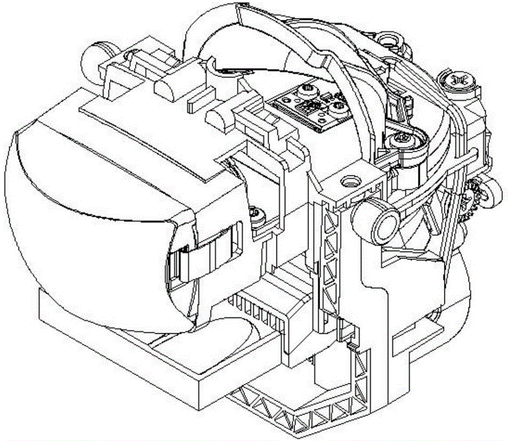
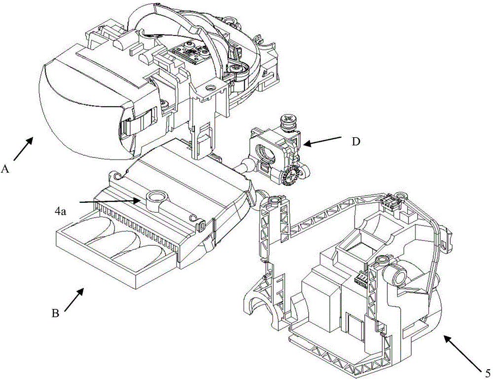
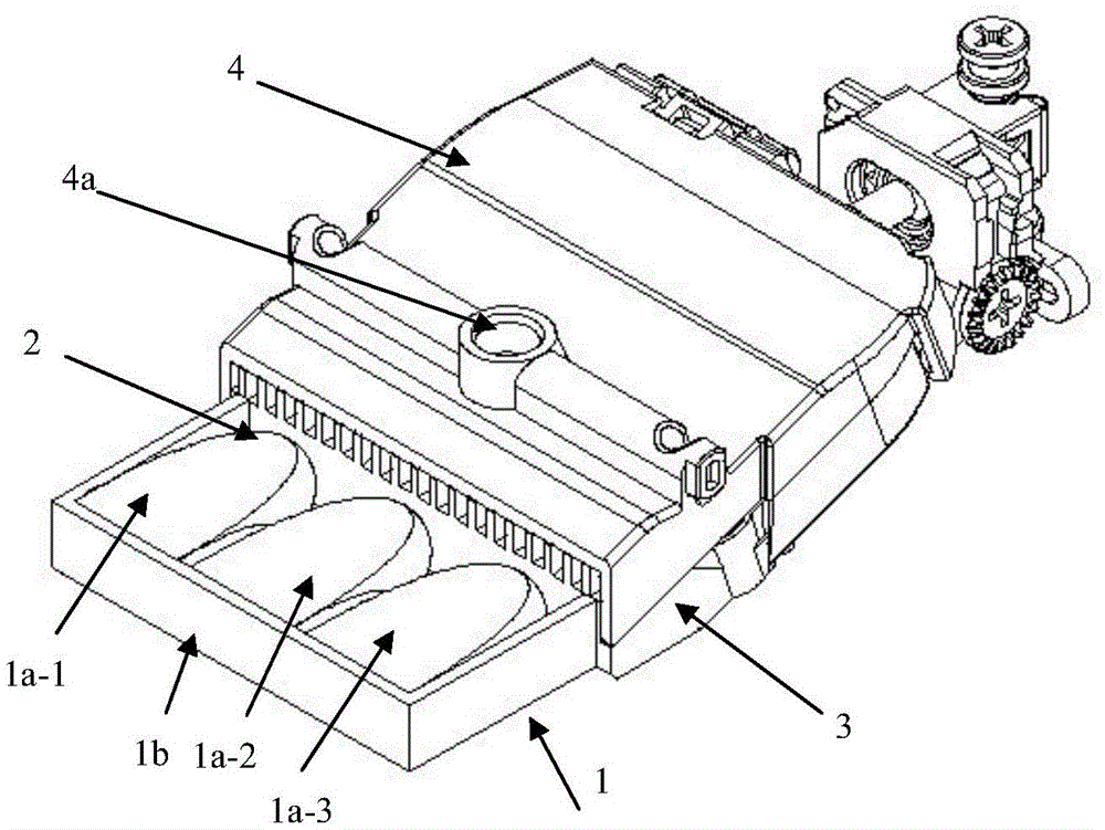
[0068] A schematic diagram of a far and near beam lighting system of the present invention is as Figure 1-Figure 7A , Figure 7B As shown, it consists of low beam unit A, high beam unit B, adjustment assembly and bracket assembly D. Through forward or reverse driving, the adjustment component can drive the high beam unit B to rotate left and right with 4a as the rotation center, that is, to adjust the left and right positions of the high beam shape.

[0069] The light shape F4 emitted by the low beam unit A is as follows Figure 5 shown. The high beam light shape is composed of light shape F1 and light shape F2, F3. The high beam light shape and the low beam light shape form the lighting light shape.

[0070] When the vehicle detects that there is an approaching vehicle on the road ahead, it sends a signal to the headlights, and the lights turn off the LED light source 2 corresponding to the multi-material lens 1a (1a-1 or 1a-2, 1a-3) to form adaptive high beam lighting T...


PUM


Abstract

The invention provides an automotive lamp self-adaptive dimming mechanism and a dimming method of the dimming mechanism. The automotive lamp self-adaptive dimming mechanism comprises a low beam unit (A) and a high beam unit (B), wherein the low beam unit (A) forms a low beam light shape, and the high beam unit (B) forms a high beam light shape. A lens forming the high beam unit (B) comprises n optically dense medium lens bodies (from 1a-1 to 1a-n) and corresponding to LED light sources, so that n high beam light shapes (from F1 to Fn) are formed, wherein the n lens bodies are optically dense medium lens bodies, and optically thinner medium lens bodies (1b) are arranged on the periphery of the n dense medium lens bodies and space the side portions of the n optically dense medium lens bodies. Adjusting assemblies (5) drive the high beam unit (B) to rotate leftwards and rightwards around a rotation center (4a), in this way, when a camera detects that an automobile comes from the opposite side or an automobile exists in the front, one or more LED light sources of the thinner medium lens bodies corresponding to the n high beam light shapes (from F1 to Fn) are extinguished, so that a plurality of high beam light shapes with vertical light and shade cut-offs are formed, and then a high beam avoids the automobile on the opposite side or in the front through the leftward rotation and rightward rotation of the high beam unit.

Description

technical field [0001] The invention relates to a vehicle lamp device, in particular to an adaptive dimming mechanism and a dimming method for a vehicle lamp adaptive high beam lighting system. The invention utilizes the principle that light is injected from an optically dense medium into an optically sparse medium to produce total reflection, combined with the on-off control of multiple LED light sources, to realize the illumination light shape required by the self-adaptive high-beam lighting system, and at the same time control the The position of the light illumination light shape, and the final adaptive high beam illumination light shape is realized through the combination of the left and right light shapes. Background technique [0002] The adaptive headlight lighting system can switch to different lighting modes according to road conditions, such as highway mode, urban road mode, country road mode, high beam lighting mode and adaptive high beam lighting mode, etc. The...

Claims


Application Information

Patent Timeline
IPC IPC(8): F21V5/04F21V14/02F21W101/02F21W101/10F21Y101/02F21W107/10
CPCF21S41/285F21S41/657F21W2102/00F21W2107/10
Inventor 张洁
Owner HASCO VISION TECHNOLOGY CO LTD
Learn More