Burner arrangement and method for operating a burner arrangement

A burner and burner technology, applied in the direction of combustion methods, burners, gas turbine devices, etc., can solve the problems of high life cycle cost, high NOx emission level, etc., and achieve the effect of good mixing characteristics

Active Publication Date: 2015-02-25
ANSALDO ENERGIA SWITZERLAND AG
View PDF12 Cites 6 Cited by
  • Summary
  • Abstract
  • Description
  • Claims
  • Application Information

AI Technical Summary

Problems solved by technology

As a result, high NOx emission levels

Method used


Image

  • Burner arrangement and method for operating a burner arrangement
  • Burner arrangement and method for operating a burner arrangement
  • Burner arrangement and method for operating a burner arrangement

Examples


Embodiment Construction

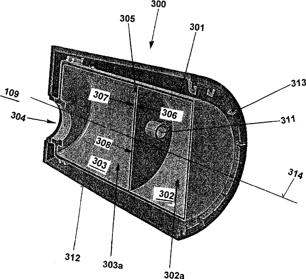
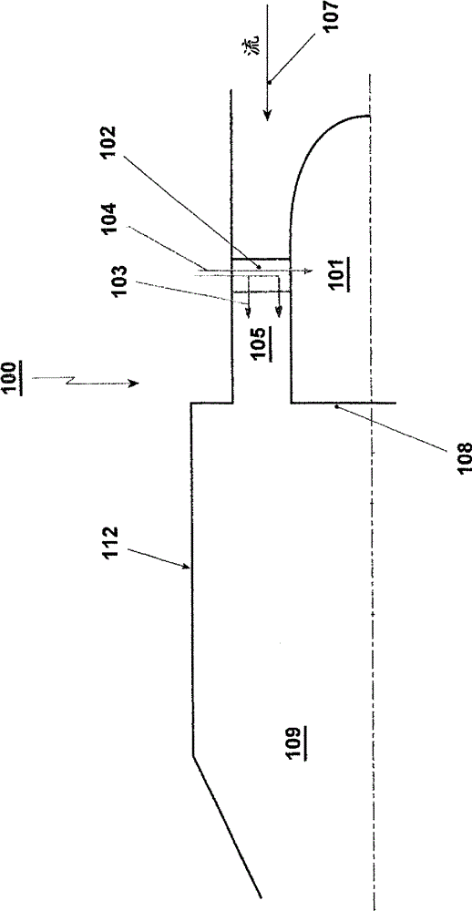
[0054] figure 1 A reheat burner arrangement 100 incorporating a center body 101 is shown. The shown center body starts upstream of the injection plane 102 (lobe), causing fuel 103 and carrier gas 104 to be injected into the center body 101 , and then the center body continues downstream to the outlet 108 of the burner arrangement 100 . The central body 101 is actively connected to the main flow 107 of hot gas. The center body 101 provides better mixing, matching the burner and burner zone. With regard to the premix burner according to the invention, the central body 101 may be provided with a fuel supply line (not shown). The central body 101 presents at its end 108 a cylindrical or quasi-cylindrical end relative to the cross-sectional area between the annular duct 105 and the combustion chamber 109 behind it in the direction of flow of the main flow 107 . A full, partial or intermediate conical configuration of the surface of the central body relative to the cross-sectiona...


PUM


Abstract

Second stage can annular burner arrangement of a sequential gas turbine comprising: a combustion zone; a center body (101) burner, located upstream of the combustion zone, and having an annular duct with a mixing zone having a cross section area; intermediate lobes (102) which are arranged with respect to the center body (101) burner as bond-bridge in circumferential direction, perpendicular or quasi-perpendicular and in longitudinal or quasi-longitudinal direction to the main mass flow, and which are actively connected to the cross section area of the mixing zone. Cooling air (104) is guided through a number of pipes within the lobes (102) to the center body and cools beforehand at least the front section (201) of the center body (101) based on impingement cooling (203). Subsequently, the impingement cooling air cools the middle face (204) and back face (202) of the center body (101) based on convective and/or effusion cooling (205). At least the back face (202) of the center body includes on the inside at least one damper (300).

Description

technical field [0001] The present invention relates to a burner arrangement for use in a single combustion chamber or in a can combustor comprising a center body burner located upstream of the combustion zone, an annular duct having a cross-sectional area, a burner along the center body The burner is arranged in the circumferential direction and the longitudinal direction of the intermediate vane, wherein the vane is actively connected to the cross-sectional area of ​​the annular duct. Furthermore, the invention relates to a method for operating a burner arrangement. Background technique [0002] To achieve high efficiency, high turbine inlet temperatures are used in standard gas turbines. As a result, high NOx emission levels and high life cycle costs occur therein. This can be mitigated by using a continuous combustion cycle where the compressor delivers almost double the known pressure ratio. The main flow passes through a first combustion chamber (for example using a...

Claims


Application Information

Patent Timeline
IPC IPC(8): F23R3/28F23R3/42
CPCF23R2900/03044F05D2220/32F23R3/346F23R2900/03043F23C7/004F23R3/46F02C3/14F23R3/286F23R3/28F23R3/36F23D2900/14004F05D2240/35F23R3/20F23R2900/03341F23D2900/14021F23R3/42F05D2260/201F05D2260/232F23R2900/03041F23R2900/00014
Inventor 高仙峰U.本兹A.特尤尔R.库卡尼
Owner ANSALDO ENERGIA SWITZERLAND AG
Why Eureka
Try Eureka