Eureka AIR delivers breakthrough ideas for toughest innovation challenges, trusted by R&D personnel around the world.

Intrinsic frequency measuring method for long and thin object

A technology for natural frequency and slender objects, applied to measuring devices, measuring ultrasonic/sonic/infrasonic waves, instruments, etc., can solve the problems of inapplicability and difficulty in distinguishing the natural frequencies of longitudinal waves or transverse waves, etc., and achieve accurate measurement results

Active Publication Date: 2015-02-25
HARBIN INST OF TECH SHENZHEN GRADUATE SCHOOL
View PDF3 Cites 14 Cited by
  • Summary
  • Abstract
  • Description
  • Claims
  • Application Information

AI Technical Summary

Problems solved by technology

The traditional natural frequency measurement methods generally use hammering, air cannon, laser ablation, or piezoelectric sensor excitation, and use piezoelectric acceleration sensor to detect the guided wave signal propagating in the structure; however, these methods are contact excitation and detection The method does not allow a large distance between the sensor and the measured object, which is not applicable to the measured objects such as pipes with outer cladding and steel wire ropes with uneven outer surfaces.
At the same time, the above-mentioned contact detection method also has a disadvantage, that is, because the generated vibration signal contains both longitudinal waves and transverse waves, it is difficult to distinguish the natural frequencies corresponding to longitudinal waves or transverse waves according to the detection signals.

Method used


Image

  • Intrinsic frequency measuring method for long and thin object
  • Intrinsic frequency measuring method for long and thin object
  • Intrinsic frequency measuring method for long and thin object

Examples


Embodiment Construction

[0032] The present invention will be further described below in conjunction with the accompanying drawings and specific embodiments.

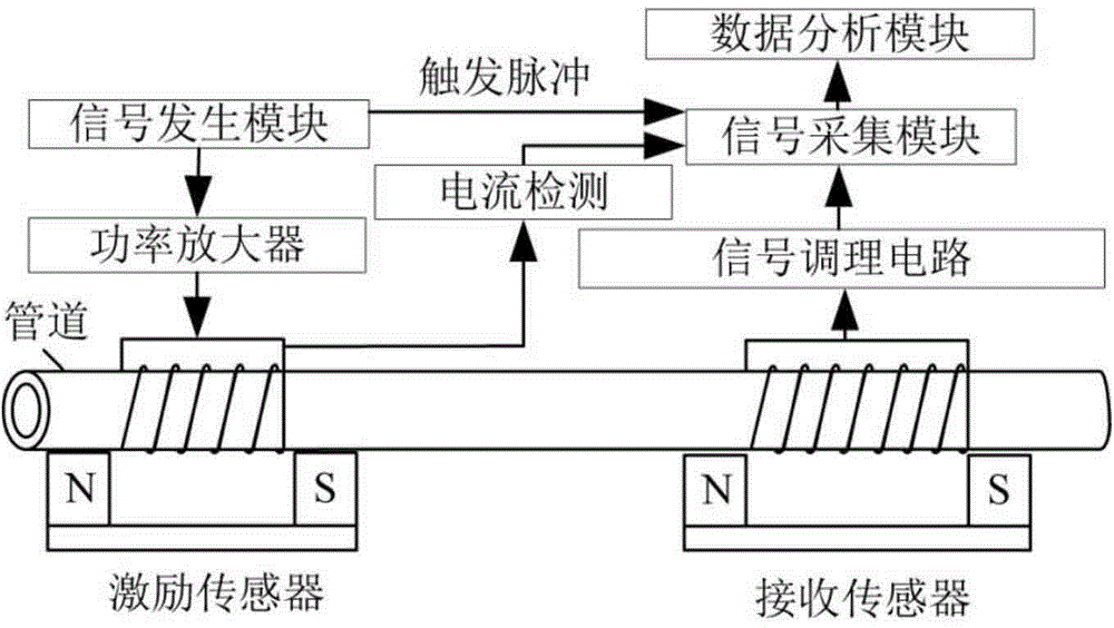
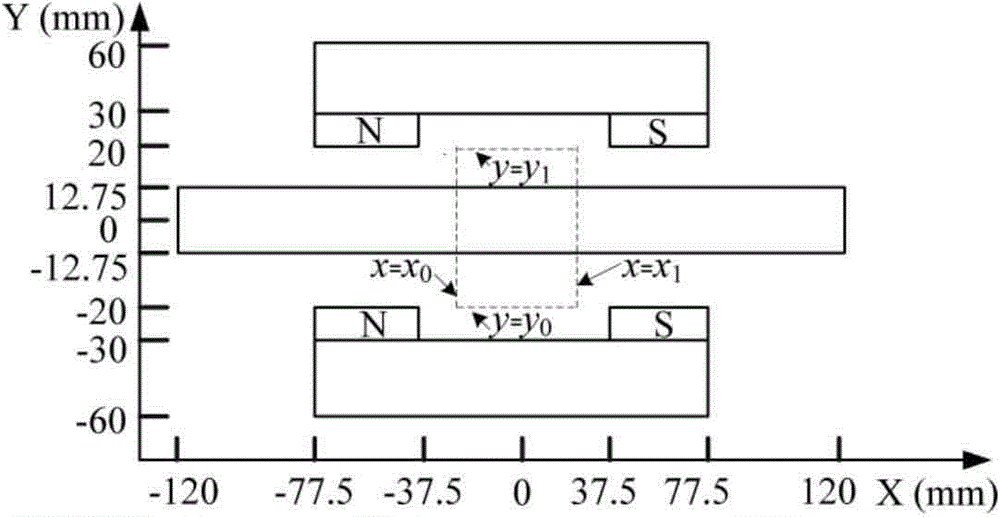
[0033] as attached figure 1 Shown is a measured pipeline longitudinal vibration natural frequency measuring device adopted by the present invention, wherein N and S respectively represent the two poles of the bias magnetic field, N is an N pole, and S is an S pole; the device includes the following modules:

[0034] Signal generation module: use a combination of a microcontroller and a signal generation circuit to generate a pulse signal that triggers the signal acquisition module and a wide-spectrum pulse excitation signal that is output to the power amplifier;

[0035] Power amplifier: composed of operational amplifiers and power devices to generate the excitation current i(t);

[0036] Sensors: including excitation sensors and detection sensors, which are composed of a bias magnetic field and a coil respectively. The bias magnetic field is ...


PUM


Abstract

The invention provides an intrinsic frequency measuring method which can be widely used for measuring the intrinsic frequency of structures which are formed by permeability magnetic materials such as pipelines, anchor rods, steel wire ropes, stay cables, plates and tanks or non-permeability magnetic materials. According to the intrinsic frequency measuring method, contact type or non-contact type excitation and detection of a vibration signal are achieved by means of a sensor according to the magnetostrictive effect and the inverse magnetostrictive effect, so that the Fourier spectrum distribution curve corresponding to a system frequency response function H[a],[b] (f) is obtained, and the peak point of the Fourier spectrum distribution curve corresponding to the system frequency response function H[a],[b] (f) is determined, so that the intrinsic frequency of a system is obtained, wherein a is a measure point, and b is an excitation point. According to the intrinsic frequency measuring method, contact measurement is available, measurement of the lift-off distance between a large sensor and an object to be measured is also available, weak vibration signals can be detected, and the intrinsic frequency measuring method has a broad application prospect in intrinsic frequency measurement.

Description

technical field [0001] The invention belongs to the field of non-destructive testing, in particular to a method for measuring natural frequency. Background technique [0002] Pipelines, tanks, etc. are important fluid transportation media, and have been widely used in the transportation of oil, natural gas, water, etc.; steel wire ropes, anchor rods, stay cables, etc. in the drilling platform. However, when components such as pipelines and steel wire ropes are subjected to external continuous excitation forces such as external wind loads and transported fluid vibrations, once the frequency of the excitation force is close to its natural frequency, it will cause coupling resonance between the fluid and the structure, and the internal stress of the material will easily reach The limit of strength will cause damage to the material and reduce its service life. Therefore, in order to improve the safety of structure operation and avoid the damage of external excitation force, th...

Claims


Application Information

Patent Timeline
IPC IPC(8): G01H11/04
Inventor 张东来周智慧
Owner HARBIN INST OF TECH SHENZHEN GRADUATE SCHOOL
Why Eureka
Eureka Blog
Learn More