
Wireless signal-to-infrared control conversion apparatus

A wireless signal and conversion device technology, applied in signal transmission systems, non-electrical signal transmission systems, instruments, etc., can solve the problems of users spending more time, troublesome use, difficult identification, etc., and achieve convenient and optimal control Position and effect, easy-to-use effect

Inactive Publication Date: 2015-02-25
陈益祥
View PDF0 Cites 4 Cited by
  • Summary
  • Abstract
  • Description
  • Claims
  • Application Information

AI Technical Summary

Problems solved by technology

[0003] However, after buying more and more infrared control products, users will generate a bunch of infrared remote controllers at home or in the company, and many infrared remote controllers are not interchangeable with each other and most of the infrared remote controllers are The shape of the infrared ray is too similar. After too many infrared controllers are gathered together, it will increase the difficulty of identification when using it. In addition, another problem with the infrared ray is that the remote control must be within a certain distance during its control operation. The control point transmits signals, and there should be no obstacles between the transmitting point and the control point, so that the control will be accurate. If the battery power is insufficient, the distance is too far, or obstacles are encountered in the remote control space, it will cause poor or uncontrollable control. situation, causing trouble in the use of
[0004] Especially under the emphasis on energy saving and carbon reduction, products that are controlled by infrared rays are generally sold on the market. Even if some products, such as air conditioners or TV equipment, have a switch device for setting the timing, it still takes time to set it through infrared on-site operation. Once you forget to set the timing or the user temporarily leaves and forgets to turn off the device, the user must spend more time turning off the power, or suffer from wasted electricity. These situations often happen to many users and are not uncommon. Although infrared It has many shortcomings mentioned above, but objectively, infrared remote control is still the most economical wireless control method. It is also the most common specification product nowadays, and it is also the biggest problem that the long-distance control technology such as WiFi cannot be widely used for product control. It is replaced by other technical solutions, so how to provide a relay long-distance remote control device that can be easily installed by consumers and directly applicable to the specifications of existing infrared remote control products is an important technical issue.
[0005] In order to solve the aforementioned problems, a remote control device with integrated infrared and Bluetooth interfaces has been developed on the market today. Through the bluetooth interface, it can be connected with the bluetooth interface of the hand-held device, thereby converting the bluetooth control signal sent by the hand-held device into the infrared control signal of the remote control electrical appliance, and using the signal of the infrared transmitter to control the corresponding The electric appliance to be controlled remotely, however, the remote control device is designed to control multiple electric appliances at the same time, therefore, its placement position is to be placed at the center formed by the positions of the electric appliances to be controlled, so as to transmit control towards different angles signal, but such a placement design is fundamentally difficult to accurately transmit the remote control signals from each infrared end to the infrared receiving end of each electrical appliance, and in the process, due to the existence of distance, there are barriers, so there are still poor control signals and other shortcomings

Method used


Image

  • Wireless signal-to-infrared control conversion apparatus
  • Wireless signal-to-infrared control conversion apparatus
  • Wireless signal-to-infrared control conversion apparatus

Examples


Embodiment Construction

[0020] Exemplary embodiments will now be described in detail with reference to the accompanying drawings. In order to simplify the description with reference to these drawings, the same or equivalent components will have the same reference numerals, and a description thereof will not be repeated.

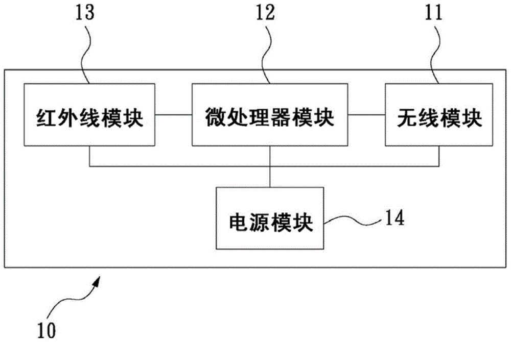
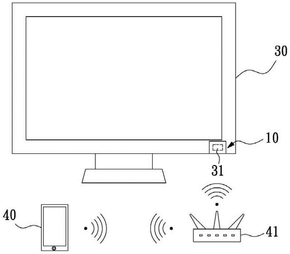
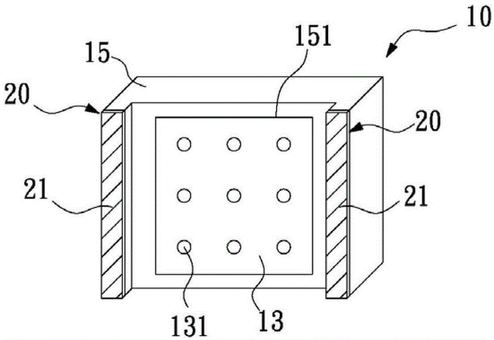
[0021] Please refer to Figure 1 to Figure 3 The first embodiment of the present invention shown is a conversion device for wireless signal to infrared control of the present invention, wherein the control structure 10 includes: a wireless module 11, a microprocessor module 12, an infrared module 13, a power supply module 14, and a wireless module 11. The microprocessor module 12 and the infrared module 13 are fixed in the casing 15 after being electrically connected in sequence, and the power supply module 14 is electrically connected and supplies power to the wireless module 11, the microprocessor module 12 and the infrared module 13 for operation .

[0022] The wireless module ...


PUM


Abstract

The invention provides a wireless signal-to-infrared control conversion apparatus. The apparatus comprises a wireless module, a microprocessor module, an infrared module, a power supply module and a shell, the wireless module, the microprocessor module and the infrared module are sequentially electrically connected, and the power supply module is electrically connected with and powers up the wireless module and power supply, the microprocessor module and the infrared module, wherein the wireless module is connected with a handheld device, receives the wireless control signal of the handheld device, and transmits the wireless control signal to the microprocessor module; the microprocessor module receives the wireless control signal from the wireless module, converts the wireless control signal into a control signal, and transmits the control signal to the infrared module; the infrared module receives the control signal processed by the microprocessor module, and emits an infrared control signal; and the shell is arranged outside an electric appliance infrared receiving end.

Description

technical field [0001] The invention relates to a device for wireless remote control electrical appliances, in particular to a conversion device for converting wireless signals into infrared control. Background technique [0002] With the development of science and technology, the use of various electrical products is becoming more and more frequent. In the case of a large number of electrical products, a large number of remote controls are used to switch functions and power switches. Electronic products such as touch-sensitive mobile phones can perform more and more functions, and products on the market are beginning to be developed as devices controlled through the network, but most of the home appliances still use the lowest-cost infrared (R / C) in terms of physical technology. Control-based, especially for relatively uncomplicated electrical equipment, in order to make operation more convenient, an increasing proportion of household appliances or electrical appliances hav...

Claims


Application Information

Patent Timeline
Patent Type & Authority Applications(China)
IPC IPC(8): G08C17/02G08C23/04
Inventor 陈益祥陈益轩
Owner 陈益祥
Learn More