
Display substrate driving device and method and display device

A driving device and display substrate technology, applied in static indicators, instruments, etc., can solve problems such as liquid crystal capacitance changes, picture display quality problems, compensation circuit burnout, etc., achieve uniform compensation and suppression, ensure picture display quality, and solve heat generation problem effect

Inactive Publication Date: 2015-02-25
BOE TECH GRP CO LTD +1
View PDF13 Cites 16 Cited by
  • Summary
  • Abstract
  • Description
  • Claims
  • Application Information

AI Technical Summary

Problems solved by technology

[0004] In the existing display structure, there is a coupling capacitance between the data line and the common electrode line (Vcom line), and the design of the high-load product determines that the coupling capacitance is very large, which also causes the common electrode line When the data is written in the line, it will be affected by the coupling of the data line, so that the phenomenon of coupling with the data line occurs, that is, the voltage of the common electrode signal fluctuates with the polarity and strength of the data signal transmitted by the data line
Then, when the voltage value of the common electrode signal is changed, the plate difference of the liquid crystal capacitor will change, which will cause problems such as cross-talk and green screen on the display device, resulting in problems with the display quality of the screen.
[0005] In the prior art, the common electrode compensation technology is used to solve the voltage fluctuation of the common electrode signal. However, due to the high voltage of the common electrode signal, the temperature of the compensation circuit is high, which may easily cause the compensation circuit to burn out.

Method used


Image

  • Display substrate driving device and method and display device
  • Display substrate driving device and method and display device
  • Display substrate driving device and method and display device

Examples


Embodiment Construction

[0039] In order to make the purpose, technical solutions and advantages of the embodiments of the present invention more clear, the following will clearly and completely describe the technical solutions of the embodiments of the present invention in conjunction with the drawings of the embodiments of the present invention. Apparently, the described embodiments are some, not all, embodiments of the present invention. All other embodiments obtained by those skilled in the art based on the described embodiments of the present invention belong to the protection scope of the present invention.

[0040] Unless otherwise defined, the technical terms or scientific terms used herein shall have the usual meanings understood by those skilled in the art to which the present invention belongs. "First", "second" and similar words used in the patent application specification and claims of the present invention do not indicate any order, quantity or importance, but are only used to distinguis...


PUM


Abstract

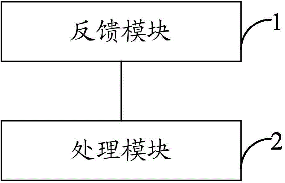
The invention provides a display substrate driving device and method and a display device. The display substrate driving device comprises a feedback module and a processing module, wherein the feedback module is used for generating feedback voltage based on fluctuation amplitude of voltage of public electrode signals when the voltage of the public electrode signals in the display substrate fluctuates, the processing module is used for superposing the feedback voltage and the gamma reference voltage to generate a first gamma voltage, the first gamma voltage is used for generating and driving gray scale voltage of a pixel electrode of the display substrate, and the difference between the gray scale voltage and the fluctuated voltage of the public electrode signals meets the condition that luminance information displayed by pixels is kept constant. Accordingly, by adjusting the voltage of the pixel electrode, coupling fluctuation of the public electrode signals can be effectively and uniformly compensated and suppressed, image display quality of the display device is guaranteed, and the problem of heating of a compensation circuit can be effectively solved.

Description

technical field [0001] The present invention relates to the field of display technology, in particular to a display substrate driving device and a driving method, and a display device. Background technique [0002] In response to the rapid development of flat-panel displays such as Thin Film Transistor Liquid Crystal Display (TFT-LCD) and other products, large-size, high-value and low-cost technologies with high drive load products are also born: such as large-size displays, high Aperture ratio design, GOA and other display products. [0003] The basic working principle of the existing flat-panel display is that the scan lines (Scan line) are sequentially turned on row by row, and the data line (Data line) writes data into pixels when each scan line is turned on, and when a row of scan lines is turned off, the just The written data information is stored in all pixels connected to the scan line. The plate difference of the liquid crystal capacitor (Clc) (usually the voltage...

Claims


Application Information

Patent Timeline
Patent Type & Authority Applications(China)
IPC IPC(8): G09G3/36
Inventor 王洁琼
Owner BOE TECH GRP CO LTD
Learn More