
Socket electric connector, plug electric connector and electric connector combination

An electrical connector and socket technology, applied in the direction of connection, two-part connection device, and components of the connection device, etc., can solve the problems of signal interference, reduced operation accuracy, and inability to have low insertion force and high extraction force at the same time. , to achieve the effect of reducing electromagnetic interference

Inactive Publication Date: 2015-02-25
连展科技电子(昆山)有限公司
View PDF0 Cites 1 Cited by
  • Summary
  • Abstract
  • Description
  • Claims
  • Application Information

AI Technical Summary

Problems solved by technology

[0003] Due to the miniaturization design of existing electronic products, the USB socket electrical connector on the electronic product is closely adjacent to other adjacent electronic components. When transmitting signals, the shielding signal of the USB socket electrical connector itself prevents electromagnetic interference (Electro Magnetic Interference (EMI for short) protection must be properly designed to avoid signal interference with other electronic components, for example, high-frequency electrical signals are serially connected to the USB plug electrical connector connected to it through the USB socket electrical connector, or Yes, multiple adjacent USB socket electrical connectors interfere with each other, so that the electronic products equipped with USB socket electrical connectors or the external electronic products connected to the USB plug electrical connectors will reduce the accuracy of operation due to noise interference
[0004] In addition, the general USB socket electrical connector and the USB plug electrical connector must also consider the convenience of use when plugging in, such as providing low insertion force and high pull-out force when plugging in. However, the general The structure to prevent electromagnetic interference cannot have the effect of low insertion force and high extraction force at the same time

Method used


Image

  • Socket electric connector, plug electric connector and electric connector combination
  • Socket electric connector, plug electric connector and electric connector combination
  • Socket electric connector, plug electric connector and electric connector combination

Examples


Embodiment Construction

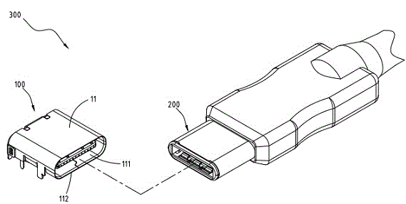
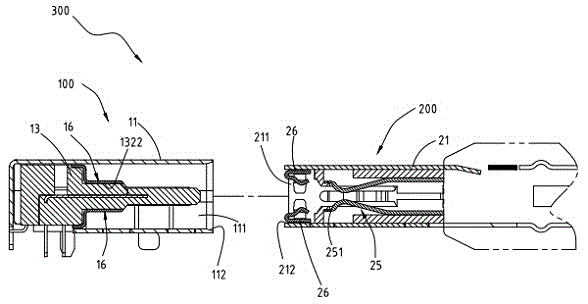
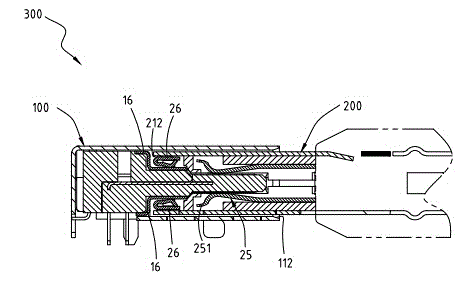
[0067] refer to figure 1 , figure 2 and image 3 , is an embodiment of the electrical connector assembly 300 of the present invention, figure 1 For the decomposition diagram, figure 2 It is a side view exploded diagram, image 3 It is a schematic diagram of side view assembly. The electrical connector assembly 300 of the present invention mainly includes a receptacle electrical connector 100 and a plug electrical connector 200 .

[0068] refer to Figure 4 and Figure 5 , especially the Figure 4 The shielding shell 11 is omitted to clearly reveal the appearance of the plurality of connecting pieces 16 located in the insulating body 13 . Here, the socket electrical connector 100 is a USB connection interface specification, and the socket electrical connector 100 mainly includes a shielding shell 11 , an insulating body 13 , a plurality of socket terminals 15 and a plurality of connecting pieces 16 .

[0069]The shielding shell 11 is a hollow shell, and the inside of...


PUM


Abstract

Provided is an electric connector combination. The electric connector combination comprises a socket electric connector and a plug electric connector, which are connected to the electric connector combination. The socket electric connector comprises a shielding housing and plural connecting sheets. The plural connecting sheets are arranged in and connected to the shielding housing. The plug electric connector comprises a shielding housing body, an insulation main body and plural press-against sheets. The insulation main body comprises a plug groove and plural penetrating grooves. The plural press-against sheets are arranged on the insulation main body, and comprise plural bodies and plural bent contact parts, which are connected with the plural press-against sheets. The plural bodies are arranged in the plural penetrating grooves and are connected with the shielding housing body. The plural bent contact parts extends into the plug groove via the plural penetrating grooves and are cooperatively pressed against the plural connecting sheets.

Description

technical field [0001] The invention relates to an electrical connector, in particular to an electrical connector combination having a socket electrical connector and a plug electrical connector. Background technique [0002] The general electrical connector interface is Universal Serial Bus (USB for short). Its plug-and-play feature is widely used by ordinary consumers, and it has been developed with the USB2.0 transmission specification to achieve faster transmission speed. The USB3.0 transmission specification. [0003] Due to the miniaturization design of existing electronic products, the USB socket electrical connector on the electronic product is closely adjacent to other adjacent electronic components. When transmitting signals, the shielding signal of the USB socket electrical connector itself prevents electromagnetic interference (Electro Magnetic Interference (EMI for short) protection must be properly designed to avoid signal interference with other electronic co...

Claims


Application Information

Patent Timeline
IPC IPC(8): H01R24/00H01R13/6583
CPCH01R12/82H01R13/6583H01R24/00
Inventor 高雅芬蔡侑伦王文郁蔡文贤艾伦麦道格
Owner 连展科技电子(昆山)有限公司
Features
  • Generate Ideas
  • Intellectual Property
  • Life Sciences
  • Materials
  • Tech Scout
  • Unparalleled Data Quality
  • Higher Quality Content
  • 60% Fewer Hallucinations
Learn More