Power cable paying-off support

A power cable and electric technology, applied in the direction of cable laying equipment, etc., can solve the problems of time-consuming, uneconomical, high center of gravity, etc., and achieve the effects of saving laying personnel, convenient loading and unloading, and low center of gravity

Inactive Publication Date: 2015-02-25
STATE GRID CORP OF CHINA +1
View PDF6 Cites 4 Cited by
  • Summary
  • Abstract
  • Description
  • Claims
  • Application Information

AI Technical Summary

Problems solved by technology

[0002] As power cables are widely used on power supply lines, more and more power cables are laid and repaired, but more than 80% of the cables are less than 100 meters long, and it is often necessary to lay a power cable of tens of meters. However, it is labor-intensive, time-consuming, and uneconomical to transport hundreds of meters or the entire power cable to the construction site or directly coil the power cable in the carriage, and use the crowd tactics to lay it on the construction site.
In the transportation and laying of power cables in China, traditional vertical pay-off brackets have been used to lay power cables. Its disadvantages are high center of gravity, heavy quality, complicated operation, low technical content, single function, labor-intensive, time-consuming, and very expensive. economy

Method used


Image

  • Power cable paying-off support
  • Power cable paying-off support

Examples


Embodiment Construction

[0012] The power cable pay-off bracket of the present invention will be further described below in conjunction with the accompanying drawings and specific embodiments:

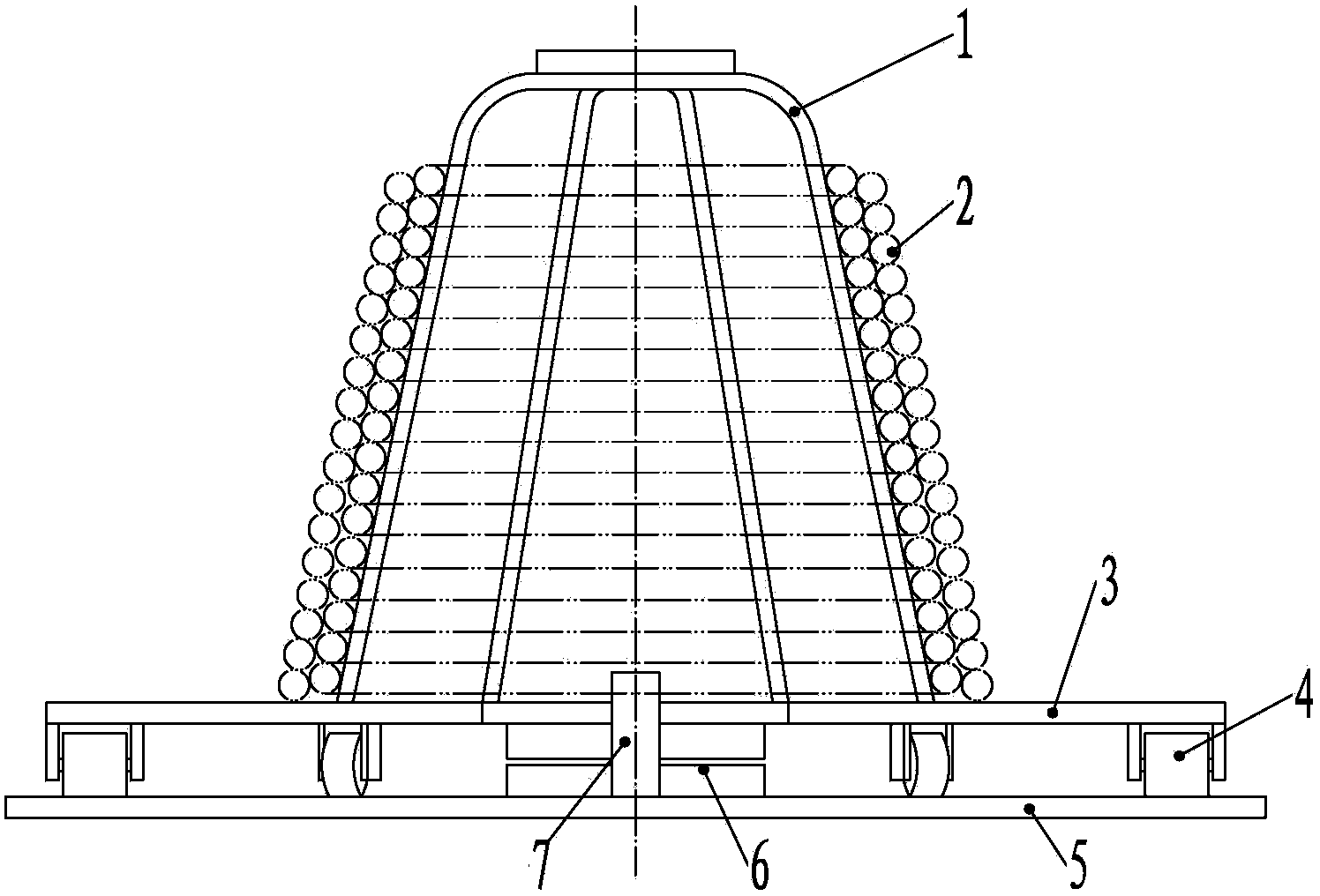
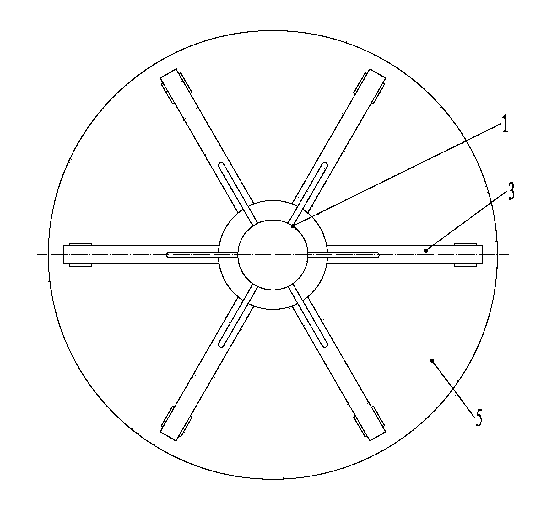
[0013] figure 1 It is a structural schematic diagram of the power cable pay-off bracket of the present invention, figure 2 yes figure 1 top view. In the figure, this power cable pay-off support includes a chassis 5, a rotating shaft 7 is arranged at the center of the chassis 5, a turntable frame 3 is arranged above the chassis 5, and a supporting roller 4 is arranged on the bottom surface of the outer ring of the turntable frame 3, and the turntable An electric brake 6 is arranged between the frame 3 and the chassis 5, the electric brake 6 is installed at the rotating shaft 7, the lower plate of the electric brake 6 is fixed on the chassis 5, the upper plate of the electric brake 6 is fixed on the turntable frame 3, and the turntable frame 3 The upper end face is provided with a squirrel cage frame 1. The...


PUM


Abstract

The invention discloses a power cable paying-off support. The power cable paying-off support comprises a base disc, a rotating shaft is arranged at the center of the base disc, a rotating disc frame is arranged on the base disc, supporting rollers are arranged on the bottom face of the outer ring of the rotating disc frame, an electric brake is arranged between the rotating disc frame and the base disc; the electric brake is arranged on the rotating shaft, a lower disc of the electric brake is fixed to the base disc, an upper disc of the electric brake is fixed to the rotating disc frame, and a mouse cage frame is arranged on the upper end face of the rotating disc frame. The paying-off support saves installation persons by more than 70 percent, saves time and labor and is safe and rapid.

Description

technical field [0001] The present invention relates to a kind of electric power construction equipment, more specifically relates to a kind of power cable pay-off bracket. Background technique [0002] As power cables are widely used on power supply lines, more and more power cables are laid and repaired, but more than 80% of the cables are less than 100 meters long, and it is often necessary to lay a power cable of tens of meters. However, it is labor-intensive, time-consuming, and uneconomical to transport hundreds of meters or the entire power cable to the construction site or directly coil the power cable in the carriage, and use the crowd tactics to lay it on the construction site. In the transportation and laying of power cables in China, traditional vertical pay-off brackets have been used to lay power cables. Its disadvantages are high center of gravity, heavy quality, complicated operation, low technical content, single function, labor-intensive, time-consuming, an...

Claims


Application Information

Patent Timeline
Patent Type & Authority Applications(China)
IPC IPC(8): H02G1/06
Inventor 曹晓育荆培征陈红光曹宸珲董雅峰
Owner STATE GRID CORP OF CHINA
Why Eureka
Try Eureka