
Novel power grid reactive compensation device

A compensation device, power grid technology, applied in circuit devices, reactive power adjustment/elimination/compensation, electrical components, etc., can solve the problems of low precision, capacitor oscillation switching, easy damage, etc. Oscillation, ensuring the effect of the line system

Inactive Publication Date: 2015-02-25
SUZHOU KELANCI ELECTRONICS SCI & TECH
View PDF2 Cites 4 Cited by
  • Summary
  • Abstract
  • Description
  • Claims
  • Application Information

AI Technical Summary

Problems solved by technology

However, as the only criterion for switching power capacitors, cosφ has many shortcomings
For example, when the three-phase reactive power is unbalanced, the capacitor compensation cannot meet the reactive power requirements of each phase separately; when the current is small (light load), it is easy to cause capacitor oscillation switching, etc., and the existing reactive power compensation device has insufficient accuracy. High, easy to oscillate and switch, and the capacitor branch of the capacitor cabinet is easily damaged under harmonic conditions.

Method used


Image

  • Novel power grid reactive compensation device
  • Novel power grid reactive compensation device
  • Novel power grid reactive compensation device

Examples


Embodiment

[0017] Examples: The following specific examples illustrate the implementation of the present invention, and those skilled in the art can easily understand other advantages and effects of the present invention from the content disclosed in this specification.

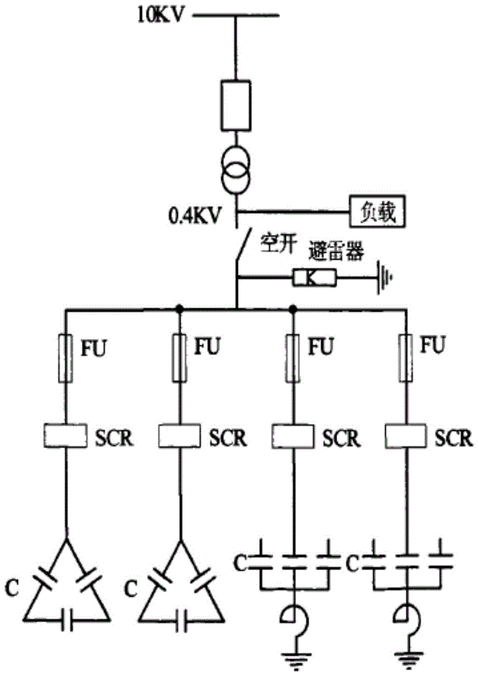
[0018] See figure 1 As shown, a new type of power grid reactive power compensation device includes a sensor unit 10, a collection and transmission controller 20, a dynamic power factor compensation controller 30, a power capacitor unit 40, and a thyristor switch unit 50. The collection and transmission controller 20 The input end of the sensor unit 10 and the dynamic power factor compensation controller 30 are connected, the output end of the collection and transmission controller 20 is connected with the dynamic power factor compensation controller 30, and the output end of the dynamic power factor compensation controller 30 is connected with a power capacitor unit 40 and thyristor switch unit 50 . The sensor unit 10 ...


PUM


Abstract

The invention discloses a novel power grid reactive compensation device. The novel power grid reactive compensation device comprises a sensor unit, an acquisition and transmission controller, a dynamic power factor compensating controller, a power capacitor unit and a silicon-controlled switch unit, wherein the sensor unit and the dynamic power factor compensating controller are connected to the input end of the acquisition and transmission controller, the dynamic power factor compensating controller is connected to the output end of the acquisition and transmission controller, and the power capacitor unit and the silicon-controlled switch unit are connected to the output end of the dynamic power factor compensating controller. According to the novel power grid reactive compensation device, oscillation is avoided, the compensation effect is guaranteed, and the compensation precision is high.

Description

Technical field: [0001] The invention relates to the technical field of reactive power compensation devices, and more specifically relates to a reactive power compensation device for a power grid. Background technique: [0002] The static capacitor cabinet is a reactive power compensation device commonly used in low-voltage power distribution systems, and the reactive power compensation controller is its core control part. Most of the old-fashioned reactive power compensation controllers use cosφ as the only judgment basis for switching power capacitors, that is, set the cosφ value of the input threshold and the cut-off threshold respectively. If it is greater than the cut-off threshold, the capacitor is cut off. However, as the only criterion for switching power capacitors, cosφ has many deficiencies. For example, when the three-phase reactive power is unbalanced, the capacitor compensation cannot meet the reactive power requirements of each phase separately; when the cur...

Claims


Application Information

Patent Timeline
Patent Type & Authority Applications(China)
IPC IPC(8): H02J3/18
CPCH02J3/1828Y02E40/10Y02P80/10
Inventor 马治远周晶晶付栋李钦锋郭建宇
Owner SUZHOU KELANCI ELECTRONICS SCI & TECH
Learn More