Engine with permanent magnetic chucks
A permanent magnetic chuck and engine technology, applied in generators/motors, machines using electric/magnetic effects, refrigerators, etc., can solve the problems of polluted environment, work efficiency, oil depletion, etc.
- Summary
- Abstract
- Description
- Claims
- Application Information
AI Technical Summary
Problems solved by technology
Method used
Image

Examples
Embodiment 1
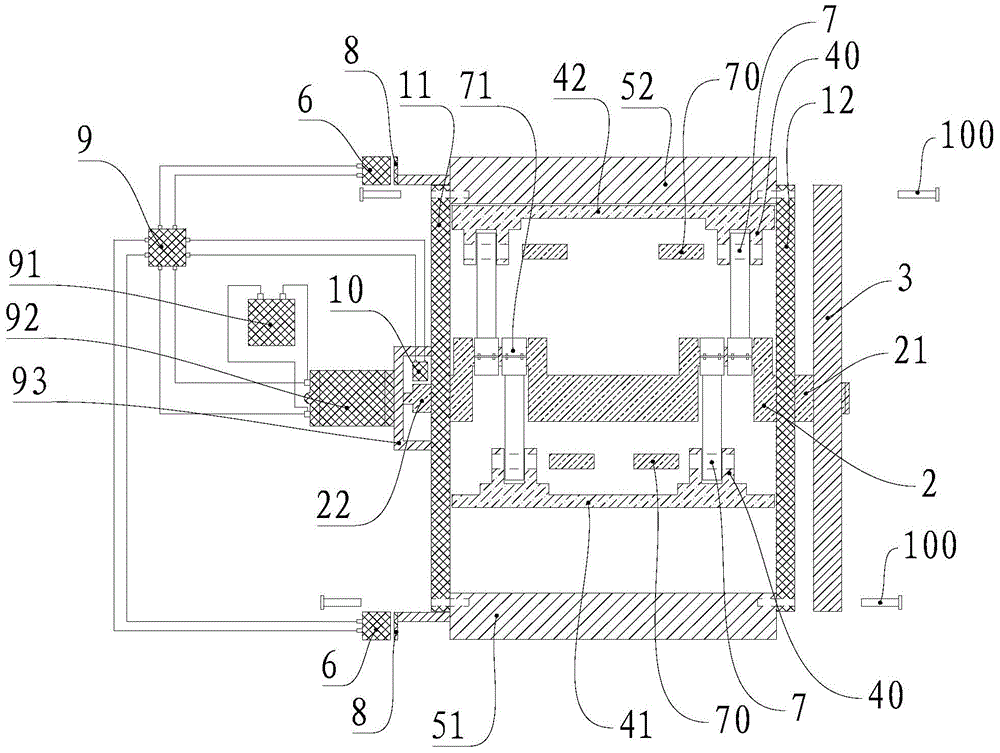
[0020] Such as Figure 1~4 Shown is a preferred embodiment provided by the present invention.
[0021] Such as figure 1 As shown, the motor provided by this embodiment includes two fixed plates (11, 12) arranged alternately. The upper end of the two fixed plates (11, 12) is provided with an upper permanent magnetic chuck 52, and the lower end is provided with a lower A permanent magnetic chuck 51, a crankshaft 2 is pierced between the two fixed plates (11, 12), and the crankshaft 2 is placed between the upper permanent magnetic chuck 52 and the lower permanent magnetic chuck 51; between the two fixed plates (11, 12) There is an upper steel plate 42 driven up and down by the upper permanent magnetic chuck 52 and a lower steel plate 41 driven up and down by the lower permanent magnetic chuck 51. The upper steel plate 42 is placed between the upper permanent magnetic chuck 52 and the crankshaft 2, and the lower steel plate 41 is placed Between the lower permanent magnetic chuck...
Embodiment 2
[0034] Such as Figure 5 Shown is another preferred embodiment provided by the present invention.
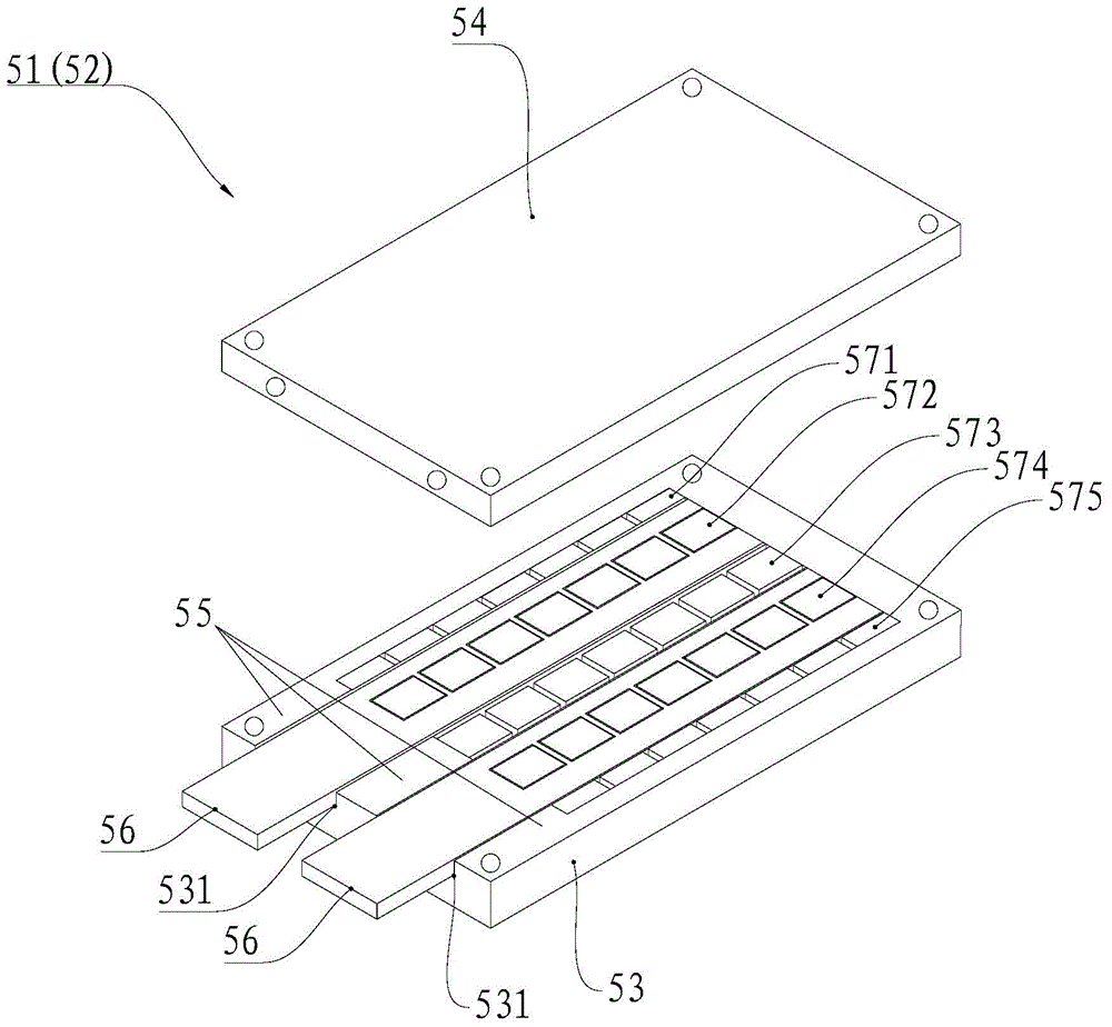
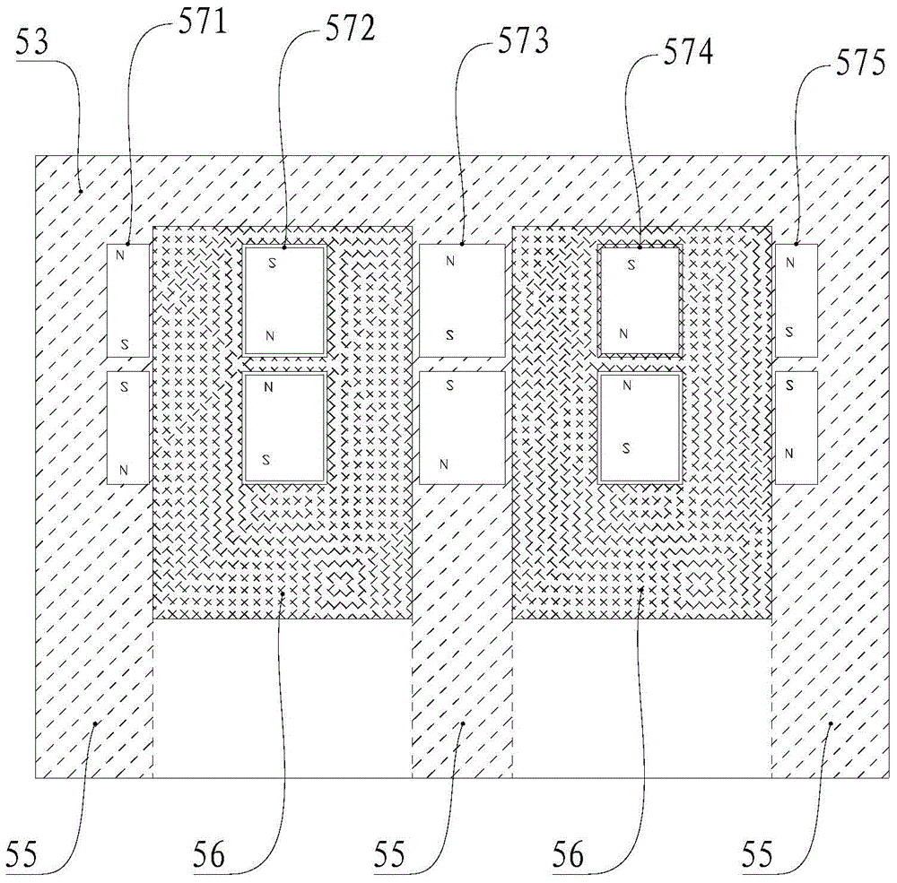
[0035] Such as Figure 5 As shown, the difference between the present embodiment and the first embodiment lies in that the driving structure in the embodiment of the present invention is the air cylinder 61 , and the air cylinder 61 is connected to the moving magnetic steel 56 . The two moving magnets 56 are connected through the second connecting plate 81 , the driving device 6 is a linear cylinder, and the piston rod of the cylinder 61 is connected with the second connecting plate 81 . When the cylinder 61 moves to the left, it drives the second connecting plate 81 to move to the left, and then drives the two moving magnets 56 to move to the left, so that the lower permanent magnetic chuck 51 or the upper permanent magnetic chuck 52 are externally strong magnetic, and the cylinder 61 moves to the right , drive the second connecting plate 81 to move to the right, and then dri...
Embodiment 3
[0037] Such as Figure 6-9 Shown is another preferred embodiment provided by the present invention.
[0038] Such as Figure 6 As shown, the difference between this embodiment and Embodiment 1 and Embodiment 2 is that the driving structure in the embodiment of the present invention includes a pneumatic piston 631, a reversing valve 632 for adjusting the direction of movement of the pneumatic piston 631, and a reversing valve connected to the reversing valve. The magnetic pole 633 on 632 and the electromagnetic coil 634 for attracting or repelling the magnetic pole 632, the electromagnetic coil 634 is located on one side of the magnetic pole 633, the air pressure piston 631 has a piston rod 6311, and the piston rod 6311 is connected to the moving magnetic steel 56. The reversing valve 632 is connected with an air pump 636. The air pump 636 provides air pressure to the reversing valve 632 and the air pressure piston 631. An air storage tank 637 is arranged between the reversing...
PUM
 Abstract
Description
Claims
Application Information
 - R&D
- Intellectual Property
- Life Sciences
- Materials
- Tech Scout
- Unparalleled Data Quality
- Higher Quality Content
- 60% Fewer Hallucinations
Browse by: Latest US Patents, China's latest patents, Technical Efficacy Thesaurus, Application Domain, Technology Topic, Popular Technical Reports.
© 2025 PatSnap. All rights reserved.Legal|Privacy policy|Modern Slavery Act Transparency Statement|Sitemap|About US| Contact US: help@patsnap.com