Intra-oral light-therapy apparatuses and methods for their use

一种口腔内、口腔的技术,应用在口内光疗装置领域,能够解决耗时或费用高等问题,达到提高速度、调节牙齿移动保持的效果

Active Publication Date: 2015-02-25
LLLT TECH CO LTD
View PDF6 Cites 21 Cited by
  • Summary
  • Abstract
  • Description
  • Claims
  • Application Information

AI Technical Summary

Problems solved by technology

Repeated visits to the doctor can be time-consuming or expensive

Method used


Image

  • Intra-oral light-therapy apparatuses and methods for their use
  • Intra-oral light-therapy apparatuses and methods for their use
  • Intra-oral light-therapy apparatuses and methods for their use

Examples


example 1

[0394] Serum vitamin D3 levels were measured in an adult male patient during his routine orthodontic checkup and recording appointment. The results of the experiment showed that the patient's serum vitamin D3 level was 20ng / ml, which was considered to be vitamin D3 deficient and abnormal. The patient's orthodontic diagnosis was grade I mild dentition crowding, with a crowding degree of 4 mm in the upper arch and 4 mm in the lower arch. An orthodontic treatment plan was developed that included the installation of fixed orthodontic appliances that slightly expand the upper and lower dental arches.

[0395] The patient took 6000 IU of oil-based vitamin D3 orally every day for 3 months to improve the serum vitamin D3 level and make the value normal. Laboratory serum tests were optionally repeated after 3 months of oral vitamin D supplementation. Patients can maintain or adjust their oral dosage of vitamin D3 according to the experimental results.

[0396] Orthodontic treatment ...

example 2

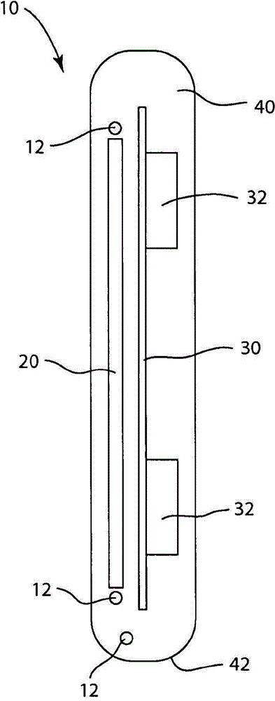
[0399] In one study, an illustrative intraoral phototherapy device of the present invention was used during the alignment phase of orthodontic treatment ( Figure 38 shown in ) irradiated the maxillary anterior teeth of 3 patients. The intraoral phototherapy device includes an intraoral housing and an LED light source. The luminescent fabric plate is embedded in the buccal silicone flange and the lingual or palatal silicone flange of the intraoral housing. The LED light source is arranged outside the patient's oral cavity. The fabric of the light-emitting panel is made by weaving acrylic optical fibers into a mat. Each patient wore their own intraoral phototherapy device, which was used in conjunction with a traditional buccal fixed orthodontic bracket treatment plan. The treatment and the results of the three patients - Patient A, Patient B and Patient C - are described in detail herein.

[0400] During the study period, each patient used the intraoral phototherapy device d...

example 3

[0414] In one study, the intraoral phototherapy device of the present invention was used during the alignment phase of orthodontic treatment ( Figure 43-44 shown) to irradiate the maxillary anterior teeth and / or mandibular anterior teeth of 9 patients (intraoral experimental group). The intraoral light therapy device includes a resilient intraoral housing with LEDs mounted on a flexible circuit and embedded in a flexible, resilient buccal flange of the intraoral housing. Each patient wears their own intraoral phototherapy device, which is used in conjunction with a conventional buccal fixed orthodontic bracket treatment plan.

[0415] During the study, each patient initially wore 0.018 slot Brackets (commercially available from Ormco Corporation, Canada, Orange), aligned with 0.014 or 0.016-inch nickel-titanium wire; later used as studies progressed 0.016" x 0.16" (also referred to as "16x16") nickel-titanium arch wire.

[0416] During the study period, each patient used ...


PUM


Abstract

In some embodiments, an apparatus comprises a housing, an emitter, and an electronic circuit. The housing is configured to fit within a patient's mouth. The emitter is at least partially encased within the housing. The emitter is configured to emit an effective amount of light to the alveolar soft tissue when the housing is disposed within the mouth. The electronic circuit is operatively coupled to the emitter. The electronic circuit is configured to control the emitter when the housing is disposed within the mouth and the apparatus is in use during orthodontic treatment. The apparatus and its use for regulating tooth movement or maintaining or improving oral tissue health are disclosed herein.

Description

[0001] Cross References to Related Applications [0002] This application claims U.S. Provisional Application No. 61 / 635,684 filed April 19, 2012, U.S. Provisional Application No. 61 / 659,168 filed June 13, 2012, and U.S. Provisional Application No. 61 / 659,168 filed June 13, 2012. Priority and benefit to U.S. Provisional Application No. 61 / 745,374 and U.S. Provisional Application No. 61 / 783,516 filed March 14, 2013, each of which is hereby incorporated by reference in its entirety. technical field [0003] The present invention generally relates to intraoral phototherapy devices and methods of use thereof, including methods for regulating orthodontic tooth movement. Background technique [0004] Orthodontics involves the movement of teeth through the bone. By applying pressure to the tooth, the bone at the front edge of the tooth is broken down to allow the tooth to move. New bone is then generated at the back edge of the tooth. Bone is resorbed (eg, decomposed) in areas o...

Claims


Application Information

Patent Timeline
Patent Type & Authority Applications(China)
IPC IPC(8): A61C19/06A61C19/04A61C7/00A61C8/00A61K31/59A61K41/00A61N5/06A61P1/02
CPCA61K31/59A61C8/0006A61N2005/0627A61C19/063A61N2005/0647A61C7/08A61B5/4836A61N2005/0663A61N2005/0662A61N2005/0606A61N2005/0659A61B5/6803A61B5/682A61N2005/0652A61N5/0603A61B5/0088A61C19/06A61N5/062A61B5/4833A61N2005/0666A61N2005/0653A61N2005/0645A61P1/02
Inventor P·布朗R·布雷登T·G·肖内西K·斯特朗格P·马修斯
Owner LLLT TECH CO LTD
Why Eureka
Try Eureka