Eureka AIR delivers breakthrough ideas for toughest innovation challenges, trusted by R&D personnel around the world.

Polyurethane spraying device

A spraying device, polyurethane technology, applied in the direction of spraying device, liquid spraying device, etc., can solve the problems of poor filling effect, difficult surface treatment, inconvenient use of high and low pressure foaming machines, etc., and achieve the effect of easy operation.

Active Publication Date: 2015-03-04
DONGGUAN XIONGLIN NEW MATERIAL TECH
View PDF10 Cites 6 Cited by
  • Summary
  • Abstract
  • Description
  • Claims
  • Application Information

AI Technical Summary

Problems solved by technology

[0002] At present, in building construction, building gaps and surrounding heat insulation, electrical equipment, gaps around pipes, and metal profile cavities of curtain walls all need to be filled to achieve the purpose of heat insulation, waterproof, and flame retardancy. The current traditional method is to use air It is very convenient to use a press to fill the gaps in the building, or use a gluer to fill, but the filling effect is not good
[0003] For some large objects with complex surface shapes or irregular surfaces, it is difficult to use the usual pouring process and equipment to treat the surface. For example, the surface of a large spherical storage tank needs to be covered with a layer of polyurethane insulation. In the case of construction, the existing high and low pressure foaming machines are very inconvenient to use

Method used


Image

  • Polyurethane spraying device
  • Polyurethane spraying device
  • Polyurethane spraying device

Examples


Embodiment Construction

[0015] The present invention will be further described below with reference to the accompanying drawings.

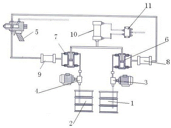
[0016] Such as figure 1 As shown, a polyurethane spraying device includes a first raw material barrel 1 and a second raw material barrel 2, the raw material in the first raw material barrel 1 is transported by the first feed pump 3, and the raw material in the second raw material barrel 2 is delivered by the second raw material barrel 2 Feed pump 4 conveys, the output pipeline of the first feed pump 3 is provided with the first metering pump 6, the output pipeline of the second feed pump 4 is provided with the second metering pump 7, the output pipeline of the first metering pump 6 Connect the first heat exchanger 8, the output pipeline of the second metering pump 7 connects the second heat exchanger 9, the output pipeline of the first heat exchanger 8 and the second heat exchanger 9 is all connected on a spray gun 5, the first The metering pump 6 and the second meterin...


PUM


Abstract

The invention discloses a polyurethane spraying device. The polyurethane spraying device comprises a first raw material bucket and a second raw material bucket; the raw material in the first raw material bucket is conveyed by a first feeding pump; the raw material in the second raw material bucket is conveyed by a second feeding pump; the output pipeline of the first feeding pump is provided with a first metering pump; the output pipeline of the second feeding pump is provided with a second metering pump; the output pipeline of the first metering pump is connected with a first heat exchanger; the output pipeline of the second metering pump is connected with a second heat exchanger; the output pipelines of both the first heat exchanger and the second heat exchanger are connected to a spray gun; the first metering pump and the second metering pump are respectively controlled by a cylinder to convey the raw materials; the air inlet and outlet pipe of the cylinder is connected with an electromagnetic valve. According to the polyurethane spraying device, raw materials in the raw material buckets are pumped into a piston cylinder by the feeding pumps under the driving of a motor, a piston move upwards to push out liquid material from an upper cylinder, materials are fed in from a lower cylinder rather than being discharged, the liquid material is discharged from the lower cylinder and the material is fed from the upper cylinder when the piston moves downwards, and the piston move up and down to realize continuous material feeding fro the spray gun.

Description

technical field [0001] The invention relates to polyurethane spraying equipment, in particular to a polyurethane spraying device. Background technique [0002] At present, in building construction, building gaps and surrounding heat insulation, electrical equipment, gaps around pipes, and metal profile cavities of curtain walls all need to be filled to achieve the purpose of heat insulation, waterproof, and flame retardancy. The current traditional method is to use air It is very convenient to use a press to fill the gaps in the building, or use a gluer to fill, but the filling effect is not good. [0003] For some large objects with complex surface shapes or irregular surfaces, it is difficult to use the usual pouring process and equipment to treat the surface. For example, the surface of a large spherical storage tank needs to be covered with a layer of polyurethane insulation. In the case of construction, the existing high and low pressure foaming machines are very incon...

Claims


Application Information

Patent Timeline
Patent Type & Authority Applications(China)
IPC IPC(8): B05B9/04B05B15/00
CPCB05B7/0416B05B7/12B05B7/2464B05B7/2472
Inventor 何建雄王一良
Owner DONGGUAN XIONGLIN NEW MATERIAL TECH
Why Eureka
Eureka Blog
Learn More