Post-tensioning chuck device

A chuck and rotary device technology, applied in positioning devices, boring/drilling devices, clamping, etc., can solve problems such as large bending deformation, easy vibration, and poor rigidity of the workpiece

Inactive Publication Date: 2015-03-04
SHAANXI QIYUAN TECH DEV
View PDF0 Cites 3 Cited by
  • Summary
  • Abstract
  • Description
  • Claims
  • Application Information

AI Technical Summary

Problems solved by technology

But there are also disadvantages, that is, the rigidity of the workpiece is poor, the bending deformation is large, and it is easy to cause vibration

Method used


Image

  • Post-tensioning chuck device

Examples


Embodiment Construction

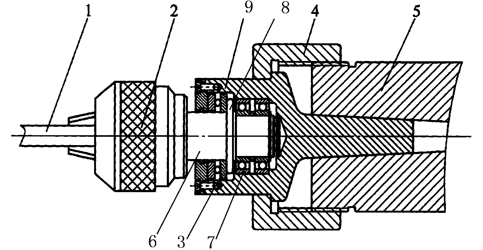
[0013] The back-pull chuck device of the present invention comprises a connection handle 9 and a connection nut 4 connected to the tailstock sleeve 5 of the machine tool, the tail of the connection handle 9 is a Morse taper handle, and the head is a cylinder with a groove. A plurality of bosses are arranged in the connecting handle 9 heads, and a boss is arranged on the outside of the connecting handle 9 heads, and a rotary device 3 is arranged in the connecting handle 9 heads, and an adjustable chuck assembly 2 is connected on the rotary device 3, which can The front end of the chuck assembly 2 is provided with a clamping claw, and a through hole is opened in the middle of the connecting nut 4, and the cylinder of the connecting handle 9 is arranged in the through hole, and one end of the connecting nut 4 is connected to the tailstock sleeve 5 through threads , the other end links to each other with the boss connecting handle 9 cylinder outsides. The rotary device 3 includes ...


PUM


Abstract

The invention provides a post-tensioning chuck device, relates to the field of a mechanical auxiliary device, and particularly relates to the post-tensioning chuck device. The post-tensioning chuck device comprises a connection handle and a connection nut, which are connected with a machine tool tailstock sleeve, and is characterized in that the tail part of the connection handle is a Mohs tapered handle and the head of the connection handle is a barrel with a groove; a plurality of lug bosses are arranged in the head of the connection handle and one lug boss is arranged on the outer side of the head of the connection handle; a rotary device is arranged in the head of the connection handle and is connected with an adjustable chuck assembly; a clamping claw is arranged at the front end of the adjustable chuck assembly. The post-tensioning chuck device is used for clamping mini-type and ultra-long type thin and long shaft workpieces when the external circles of the workpieces are turned; the workpieces are turned at a stretching state and the problem that thin and long shafts are bent by an axial cutting force can be solved; meanwhile, the bending and deformation degree, caused by a radial cutting force, is reduced under the action of the axial cutting force, and the rigidity and the machining precision of the thin and long shafts are improved.

Description

technical field [0001] The invention relates to the field of mechanical auxiliary devices, in particular to a back-pull chuck device. Background technique [0002] Compared with the general slender shaft, the miniature slender shaft is obviously more prone to force bending and vibration during processing, and the processing is more difficult. The clamping method used in the traditional processing process is: [0003] (1) "One clamp, one top" clamping means that one end of the workpiece is clamped by the spindle chuck, and the other end is supported by the top of the tailstock. This method is convenient for clamping, but because the top of the top is too tight, the workpiece is prone to top bending. At the same time, the top of the tailstock will also limit the thermal elongation caused by the cutting heat of the slender shaft, resulting in bending; [0004] (2) "Two tops" clamping adopts double tops clamping, and the clamp is driven by the spindle to drive the workpiece to ...

Claims


Application Information

Patent Timeline
Patent Type & Authority Applications(China)
IPC IPC(8): B23B5/08B23Q3/00
CPCB23B43/02
Inventor 张淑芬
Owner SHAANXI QIYUAN TECH DEV
Why Eureka
Try Eureka