Laser scribing device for shearing copper plate

A laser scribing and copper plate technology, which is applied in laser welding equipment, welding equipment, metal processing equipment, etc., can solve the problems of not being able to cut, bolts not being too tight, and copper plates not being centered, so as to prevent deflection and ensure continuous performance, compact structure

Inactive Publication Date: 2015-03-04
江苏鑫成铜业有限公司
View PDF6 Cites 2 Cited by
  • Summary
  • Abstract
  • Description
  • Claims
  • Application Information

AI Technical Summary

Problems solved by technology

However, the sensitivity of laser scribing is very high, and the bolts should not be too tight when adjusting, so the vibration of the frame will easily loosen the bolts, so the laser scribing will be deflected after a period of time, so that the copper plate cannot be centered and cannot be cut. Adjusting the laser scribing requires the shutdown of both sides of the shears, which is very time-consuming and seriously affects production

Method used


Image

  • Laser scribing device for shearing copper plate

Examples


Embodiment Construction

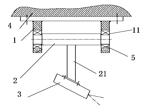
[0011] A laser scribing device for copper plate shearing, including a support 1, a swing shaft 2 and a laser scribing transmitter 3, the support is fixed on a frame 4, and mounting holes 11 are provided on the supports on both sides, The mounting holes on the supports on both sides are circular, and the centers of the two mounting holes are on the same straight line; the concentricity of the two mounting holes is guaranteed. The swing shaft is a T-shaped structure, wherein one side of the T shape is the rotating shaft, and the I side of the T shape is the mounting handle 21; the two ends of the rotating shaft are provided with mounting shafts, and the mounting shafts are installed in the mounting holes through the bearings 5; The device is set at the end of the mounting handle. The laser scribing emitter is set on the mounting handle through bolts. There are dust covers on the outside of the support, swing shaft and laser marking transmitter.

[0012] When installing, first ...


PUM


Abstract

The invention discloses a laser scribing device for shearing a copper plate. The device comprises supports, an oscillating shaft and a laser scribing transmitter, wherein the supports are fixedly arranged on a rack; circular mounting holes are formed in the supports on the two sides; the circle centers of the two mounting holes are on the same straight line; the oscillating shaft is of a T-shaped structure; one side of the T-shaped structure is a rotating shaft, and the I side of the T-shaped structure is a mounting handle; mounting shafts are arranged at the two ends of the rotating shaft, and are arranged in the mounting holes; the laser scribing transmitter is arranged at the tail end of the mounting handle. The device is compact in structure and maintenance-free, and the laser scribing transmitter can be prevented from being deviated.

Description

technical field [0001] The invention relates to a laser scribing device, in particular to a laser scribing device for copper plate cutting. Background technique [0002] The finishing line of the copper plate factory uses disc-type double-sided shears to cut the two sides of the copper plate. First, laser scribing is used to draw the shear lines on both sides of the copper plate, so as to see the amount of trimming, whether the camber is curved, etc., and determine the cutting work of the double-sided shears . At present, the laser scribing transmitter is cylindrical or cuboid, fixed on the bracket by bolts, fixing rings, etc., the bracket is installed on the rack, the rack is fixed, and the bracket and the transmitter are adjustable in three directions in space , to ensure that the laser scribing can be adjusted to the desired position. However, the sensitivity of laser scribing is very high, and the bolts should not be too tight when adjusting, so the vibration of the ...

Claims


Application Information

Patent Timeline
Patent Type & Authority Applications(China)
IPC IPC(8): B23K26/38B23K26/70
CPCB23K26/38B23K26/10B25H7/04
Inventor 王琳
Owner 江苏鑫成铜业有限公司
Why Eureka
Try Eureka