Automatic welding method based on three-dimensional model and machine vision and welding device based on three-dimensional model and machine vision

A 3D model and machine vision technology, applied in auxiliary devices, welding equipment, welding equipment, etc., can solve the problems of not having large-scale automatic search for welding seam positions, not having real-time adjustment control, not being able to adapt to thermal deformation, etc., to achieve Welding operation, fast positioning speed, and the effect of overcoming processing and assembly errors

Active Publication Date: 2015-03-04
南京曼新智能科技有限公司
View PDF12 Cites 71 Cited by
  • Summary
  • Abstract
  • Description
  • Claims
  • Application Information

AI Technical Summary

Benefits of technology

This technology helps robots perform precise tasks more efficiently while avoid colliding their own parts or other objects together due to its ability to accurately follow paths on complex surfaces like steel pipes. By capturing images from the surface being worked upon, this technology allows robotic arms to quickly identify where they are working next based on these captured data. Additionally, there's no requirement for manual setup of start points at which the wires will be joined again afterward because the robot moves around freely within the area covered by the wired connections between them. Overall, this new technique improves efficiency and precision in manufacturing processes.

Problems solved by technology

The technical problem addressed in this patented text relates to improving the functionality of robotized welders without requiring manual initialization during startup or repositioning their positions when dealing with large variations in temperature due to heat transfer from the wires being joined together.

Method used


Image

  • Automatic welding method based on three-dimensional model and machine vision and welding device based on three-dimensional model and machine vision
  • Automatic welding method based on three-dimensional model and machine vision and welding device based on three-dimensional model and machine vision

Examples


Embodiment Construction

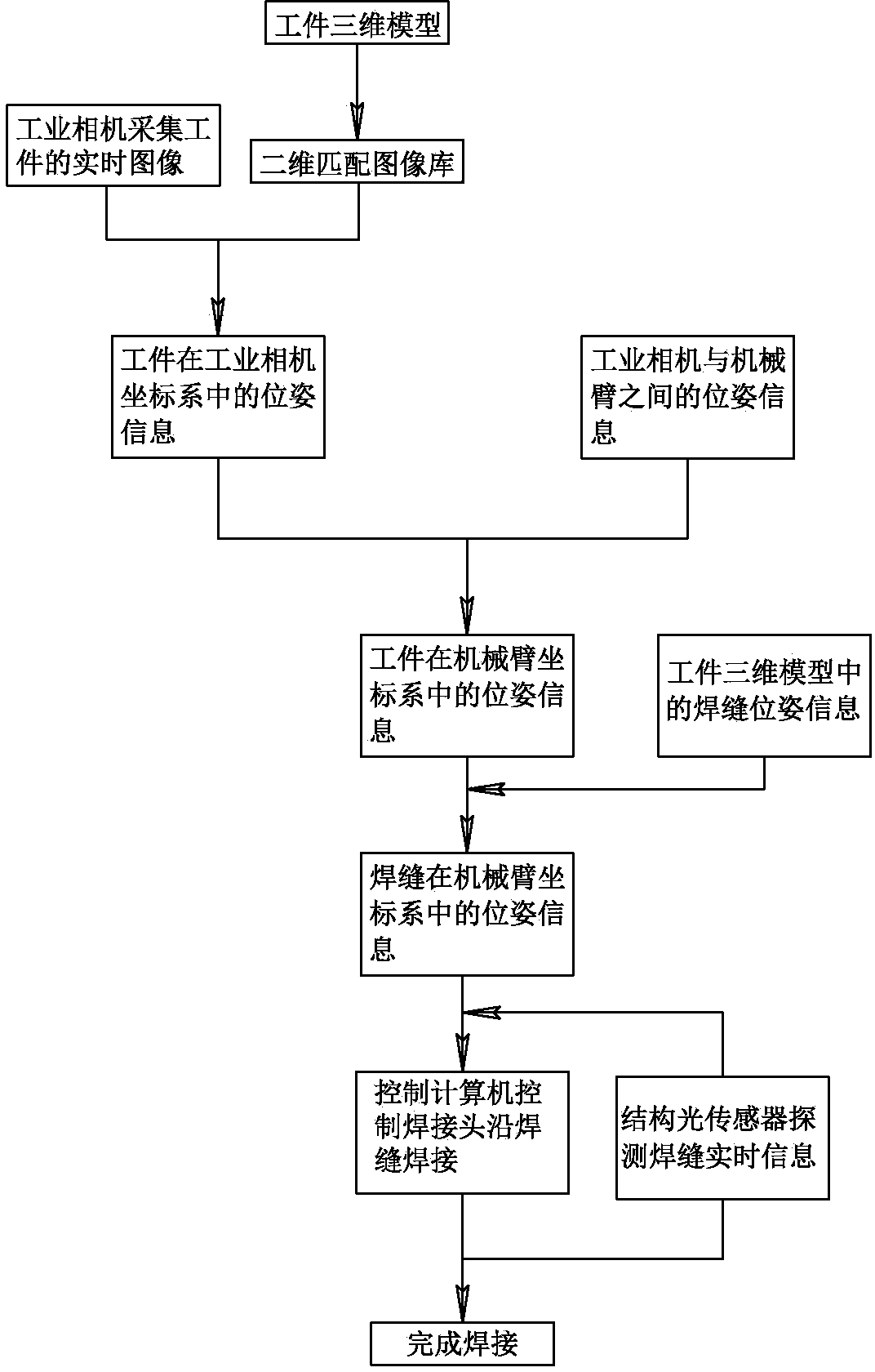
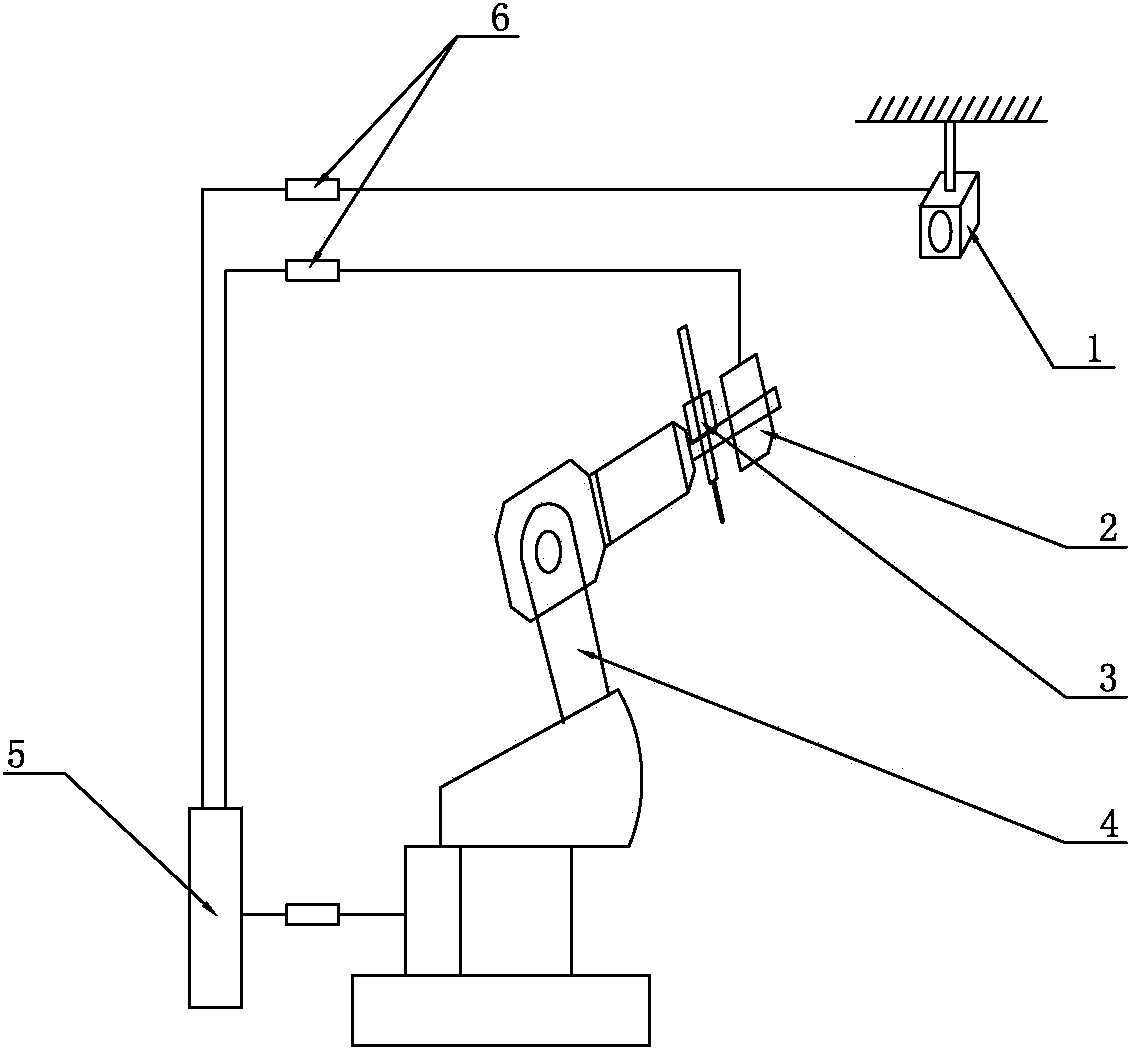
[0022] Such as figure 2 As shown, it is an automatic welding device based on a three-dimensional model and machine vision. Its structure mainly includes a mechanical arm 4 with six degrees of freedom. The six degrees of freedom are linear motions in the directions of X, Y and Z axes. , and rotation around the X, Y, and Z axes; the mechanical arm 4 holds the welding torch 3, and the end of the mechanical arm 4 is provided with a structured light sensor 2. The device also includes an industrial camera 1, and the workpiece collected by the industrial camera 1 The image signal is transmitted to the control computer 5, and the control computer 5 compares the plane figure converted from the three-dimensional model of the workpiece with the image signal collected by the industrial camera to obtain the pose information of the workpiece in the coordinate system of the industrial camera, and then according to the pose information Determine the position and orientation information of th...


PUM


Abstract

The invention relates to an automatic welding method based on a three-dimensional model and machine vision and a welding device based on the three-dimensional model and the machine vision, relating to the technical field of welding. An industrial camera is used for acquiring an image of a workpiece to be welded; three-dimensional match is carried out and the workpiece to be welded is positioned according to the three-dimensional model of the workpiece; a welding line is positioned according to welding line information in the three-dimensional model; the welding line is accurately positioned by using a structure optical sensor; a movement track of a welding gun is adjusted according to the accurate position of the welding line so as to accurately track and weld the welding line. According to the automatic welding method, an automatic positioning and tracking function of the welding line can be realized, and the reliability of tracking the welding line and the tracking precision are improved. The problems that the welding precision is influenced, caused by the fact that the workpiece is warped by thermal deformation in a welding process and the like are solved; the adjustment and the adaptation can be carried out very well and the welding quality is improved.

Description


Claims


Application Information

Patent Timeline
Owner 南京曼新智能科技有限公司
Why Eureka
Try Eureka