A cross-top cutting device based on autoclaved aerated blocks

A cutting device, autoclaved gas filling technology, applied in the direction of ceramic molding machines, manufacturing tools, etc., can solve the problems affecting the appearance quality of the finished green body, affecting the cutting dimensional accuracy of the green body, and affecting the flatness of the cutting surface, etc., to reduce the edge Corner collapse, reasonable and simple structure, and the effect of improving cutting precision

A cutting device, autoclaved gas filling technology, applied in the direction of ceramic molding machines, manufacturing tools, etc., can solve the problems affecting the appearance quality of the finished green body, affecting the cutting dimensional accuracy of the green body, and affecting the flatness of the cutting surface, etc., to reduce the edge Corner collapse, reasonable and simple structure, and the effect of improving cutting precision

CN104385446BActive Publication Date: 2017-01-11DONGYUE MACHINERY GRP

Image

  • A cross-top cutting device based on autoclaved aerated blocks
  • A cross-top cutting device based on autoclaved aerated blocks

Examples


Embodiment Construction

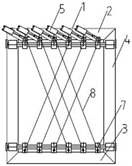
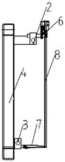
[0013] Such as figure 1 , 2 As shown, the cross-top cutting device includes a movable pre-cut frame 1, a steel wire side extension support rod 7, a clamping wire cylinder 5, and a cutting wire 8. The mobile pre-cut frame 1 includes an upper beam 2 and a lower beam 3 And the two longitudinal beams 4 connecting the upper beam 2 and the lower beam 3, the upper beam 2 is provided with six clamping wire cylinders 5 equidistantly arranged, and the clamping wire cylinders 5 are fixedly connected with the upper beam 2 through the cylinder fixing frame 6 , the lower crossbeam 3 is provided with equidistant, stepped arrangement of six steel wire side extension support rods 7, the steel wire side extension support rods 7 are fixedly connected with the lower crossbeam 3 through bolts, and the upper end of the cutting steel wire 8 is connected with the clamping wire cylinder 5 , the lower end of the cutting steel wire 8 is connected with the steel wire side extension support rod 7, and th...


PUM


Abstract

The invention discloses a cross topping and cutting device on the basis of a vapor-pressure aerating building block. The cross topping and cutting device comprises a movable pre-cutting frame, steel wire side-stretching support rods, wire clamping and staying air cylinders and cutting steel wires. Flatness of the cut surface is ensured while elastic deformation force of the cutting steel wires is concentrated in the middle of a blank, elastic stress is offset by the cross structure, and edge breakage caused by diagonally pulling the steel wires to separate from the single side is avoided; cutting accuracy is ensured by the cross cutting steel wires, lateral cross grains are eliminated, and similar cutting effect of scissors during cutting is generated. The cross topping and cutting device is novel in design, reasonable and simple in structure.

Description

technical field [0001] The invention belongs to the technical field of autoclaved aerated block production equipment, and in particular relates to a cross-top cutting device for autoclaved aerated blocks. Background technique [0002] Existing horizontal cutting machines pre-cut obliquely-stayed steel wires are mostly connected by single-rod extension type hinge points, which may easily cause vibration of the support rod during cutting and affect cutting accuracy, and single-sided obliquely-stayed steel wires are easily deformed due to the elastic deformation of the steel wires during cutting. It causes separation and chipping, which affects the appearance quality of the finished body. At the same time, when the single cable-drawn steel wire is cut by the force in the direction of cutting and walking, the deformation of the steel wire is relatively large, which will cause the shaking of the cable-drawn steel wire, resulting in oblique cutting ripples of the green body, and a...

Claims


Application Information

Patent Timeline
11 Jan 2017
Publication
CN104385446B
IPC
B28B11/14
CPC
B28B11/14
Inventors
孙京伟; 刘吉