Tire mounting structure and application method thereof

A technology for installing structures and tires, which is applied in tire installation, tire parts, transportation and packaging, etc. It can solve problems such as tire drop, large size and weight, and increase the working load of the telescopic end of lifting equipment, so as to increase the moving speed , reduce the workload, facilitate the rapid rise of the effect

Inactive Publication Date: 2015-03-04
CHENGDU XINGBODA PRECISION MACHINERY
View PDF0 Cites 4 Cited by
  • Summary
  • Abstract
  • Description
  • Claims
  • Application Information

AI Technical Summary

Problems solved by technology

[0003] In the production and assembly of motor graders, due to its large size and weight, it is generally difficult to manually move and assemble various parts
During the production, installation and disassembly process of motor grader tires, the ordinary peripheral clamping method is around the tire, and the outer ring of the tire is clamped by mechanical claws from the periphery to the middle to fix the tire. Although this clamping method can ensure that the tire It moves smoothly, but when the tire is vulcanized and other production and processing procedures, the peripheral clamping cannot meet the needs of production and processing; and in the ordinary peripheral clamping process, the mechanical jaw uses the hydraulic cylinder to clamp the tire, so that the clamping The overall weight of the head increases, which increases the working load of the telescopic end of the lifting equipment. During the clamping process, the hydraulic cylinder drives the mechanical claws to contact the tires for a rigid connection. Once the hydraulic cylinder fails, it is easy to make the clamped tire fall.

Method used


Image

  • Tire mounting structure and application method thereof
  • Tire mounting structure and application method thereof
  • Tire mounting structure and application method thereof

Examples


Embodiment 1

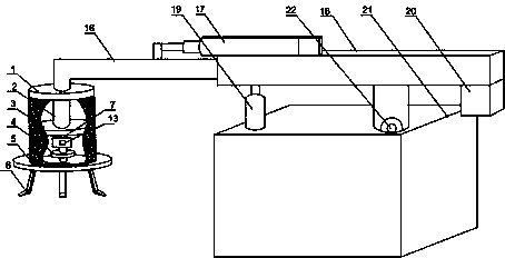
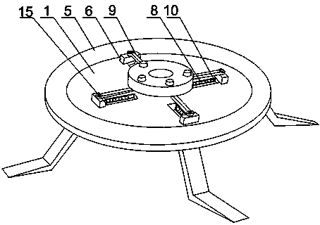
[0023] Such as Figure 1 to Figure 3 As shown, the present invention is a tire mounting structure and its use method. Put the claw 6 at the lower end of the supporting cylinder 1 into the inner ring of the tire, start the motor 2, and the output end of the motor 2 rotates to drive the turntable 4 to start rotating. The jaws 6 are hinged to the bottom of the turntable 4 through the connecting rod 9, and the connecting rod 9 drives the jaws 6 to slide freely in the horizontal groove 15. When the diameter of the jaw ring formed by a plurality of jaws 6 gradually increases, the jaws 6 Closely attached to the inner ring of the tire, and then realize the clamping and fixing of the tire; during the process of clamping the tire by the claw 6, the claw 6 is pushed to the outermost end of the horizontal groove 15 by the connecting rod 9, and the direction of the connecting rod 9 is just right Vertical to the axis direction of the turntable 4, the jaws 6 are in a self-locking state at th...

Embodiment 2

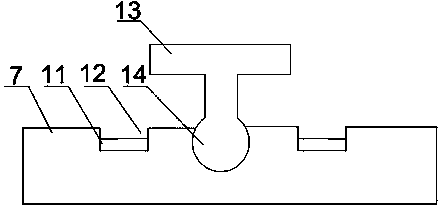
[0025] Such as image 3As shown, in this embodiment, on the basis of Embodiment 1, the limiting structure includes a limiting plate 7, the limiting plate 7 is fixed on the baffle plate 3, and a through hole is opened in the middle of the limiting plate 7, Described motor output end 14 passes through hole, has two grooves 12 on the same side of limiting plate 7, and two grooves 12 are positioned at the both sides of motor 2 output ends, is installed on motor output end 14 T-shaped block 13, travel switch 11 is installed in the groove 12, and travel switch 11 is connected with motor 2 by lead. When clamping the tire placed horizontally, the motor 2 rotates, driving the T-shaped block 13 on the motor output end 14 to rotate, and when the claw 6 slides to the outermost end of the horizontal groove 15, one end of the T-shaped block 13 Contact with the travel switch 11 in the groove 12, the travel switch 11 controls the motor 2 to stop rotating; The travel switch 11 in the groove ...

Embodiment 3

[0027] Such as figure 1 As shown, this embodiment is based on Embodiment 1. The telescopic structure includes a boom 18 and a telescopic boom 16. The boom 18 is arranged on the base 21 through a rotating shaft 22. The boom 18 is provided with a chute and a first Hydraulic cylinder 17, the output end of the first hydraulic cylinder 17 is connected with the middle part of the telescopic arm 16, one end of the telescopic arm 16 is slidably arranged in the chute, and the other end of the telescopic arm 16 is connected with the support cylinder 1; The cylinder 19 and the second hydraulic cylinder 19 are installed on the base 21 , and the output end of the second hydraulic cylinder 19 is connected with the bottom of the boom 18 . When starting to install the tire, start the first hydraulic cylinder 17, the first hydraulic cylinder 17 pushes the telescopic arm 16 to move previously, and the supporting cylinder 1 connected with the telescopic arm 16 moves accordingly, and the supporti...


PUM


Abstract

The invention discloses a tire mounting structure and an application method thereof. The sliding friction between clamping jaws and groove walls can be changed to the rolling friction by rollers, so that the loss between horizontal grooves and the clamping jaws is reduced; a motor rotates at a constant swinging angle, so that the quick movement of the clamping jaws in the horizontal grooves can be realized; and a limiting structure can keep the rotation of the output end of the motor in a fixed angle range.

Description

technical field [0001] The invention relates to a clamping tool, in particular to a tire mounting structure and a method for using the same. Background technique [0002] The grader is an earthmoving machine that uses a scraper to level the ground. It is suitable for building roadbeds and road surfaces, building side slopes, digging side ditches, mixing road surface mixtures, sweeping snow, pushing loose materials, and maintenance of dirt roads and gravel roads. Work. There are two types of motor graders: double-axis and three-axis. The commonly used one is three-axis. differential for steering. The working principle of the grader is roughly as follows: the scraper is installed under the slewing ring through two brackets, and the slewing ring can be rotated to adjust the position of the scraper; the base of the slewing ring is triangular, and its front end is hinged on the front of the main frame. The two corners are suspended in the middle of the main frame by lifting hy...

Claims


Application Information

Patent Timeline
Patent Type & Authority Applications(China)
IPC IPC(8): B62D65/00B60C25/00
CPCB60C25/132
Inventor 吴光武
Owner CHENGDU XINGBODA PRECISION MACHINERY
Why Eureka
Try Eureka