Feeding device for automatically lifting cylindrical material
An automatic lifting and transmission technology, which is applied in the direction of transportation and packaging, conveyor objects, etc., can solve the problems of increasing the risk factor of personnel, reducing production efficiency, and high operating intensity, so as to save labor costs, easy operation, and reduce operation. The effect of intensity
- Summary
- Abstract
- Description
- Claims
- Application Information
AI Technical Summary
Problems solved by technology
Method used
Image
Examples
Embodiment 1
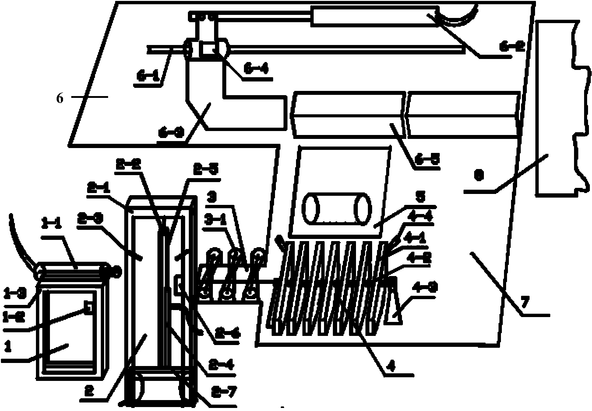
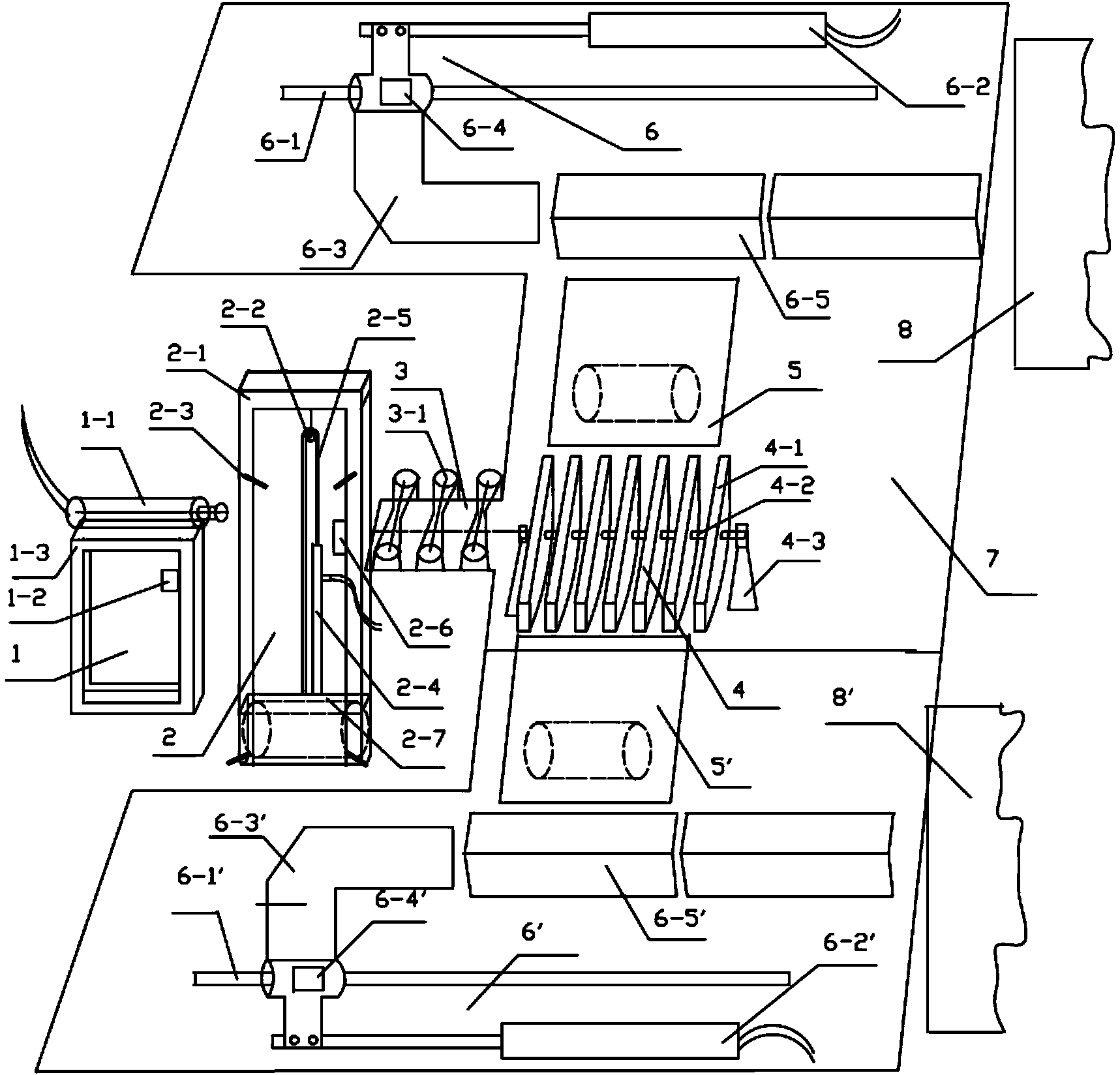
[0019] The present invention is used for cylindrical material automatic lifting feeding device, and this feeding device comprises push rod device 1, lifting device 2, transmission device 3, seesaw device 4, inclined plate 5, pushing device 6, described lifting device 2- A push rod device 1 is provided on one side, a transmission device 3 is provided on the other side of the lifting device 2, a seesaw device 4 is provided on one side of the transmission device 3, an inclined plate 5 is provided on one side of the seesaw device 4, and an inclined plate 5 is provided on one side of the inclined plate 5. A pushing device 6 is provided, and the transmission device 3 , the seesaw device 4 and the pushing device 6 are all arranged on the support plate 7 .
[0020] The push rod device 1 includes a push rod support 1-3, the top of the push rod support 1-3 is fixed with a first telescopic rod 1-1, and the push rod support 1-3 is provided with a first telescopic rod 1-1 for controlling th...
Embodiment 2
[0028] Such as figure 1 , 2 As shown, on the basis of Embodiment 1, both sides of the rocker device 4 are symmetrically provided with inclined plates 5 on the support plate 7, and correspondingly each is equipped with a push device 6. When in use, the lifting groove 2 of the lifting frame 2 -7 is located below the ground, first put the billet to be transported on the ground in front of the lifting device 2, when a billet enters the lifting groove 2-7, the staff starts the switch, the second electromagnetic pneumatic valve 2-6 works, and starts the second telescopic The rod 2-4 raises the lifting groove 2-7 through the pulley block 2-5, and after touching the first sensor 2-3 in the middle and upper part of the lifting frame, the first electromagnetic pneumatic valve 1-2 is started to work, and the first telescopic rod 1-1 Push the billet out of the lifting frame 2, enter the transmission device 3, and drive it to the seesaw device 4, then the first telescopic rod 1-1 returns,...
PUM
 Abstract
Description
Claims
Application Information
 - R&D
- Intellectual Property
- Life Sciences
- Materials
- Tech Scout
- Unparalleled Data Quality
- Higher Quality Content
- 60% Fewer Hallucinations
Browse by: Latest US Patents, China's latest patents, Technical Efficacy Thesaurus, Application Domain, Technology Topic, Popular Technical Reports.
© 2025 PatSnap. All rights reserved.Legal|Privacy policy|Modern Slavery Act Transparency Statement|Sitemap|About US| Contact US: help@patsnap.com


