Automatic lifting and feeding device for cylindrical materials

A technology of automatic lifting and transmission device, applied in the directions of transportation and packaging, conveyor objects, etc., can solve the problems of increasing the risk factor of personnel, reducing production efficiency, and high operation intensity, saving labor costs, easy operation, and reducing operation. the effect of strength

Active Publication Date: 2017-01-11
TIANJIN DONGYI MAGNESIUM PROD
View PDF5 Cites 0 Cited by
  • Summary
  • Abstract
  • Description
  • Claims
  • Application Information

AI Technical Summary

Problems solved by technology

Because the weight of cylindrical metal blanks is generally large, transfer vehicles are usually used, and the blanks can be accurately transported to the material inlet with the help of cranes. This kind of manual loading operation is intensive and cumbersome, and the crane operation and heavy object orientation are carried out Generally need 3-5 people
At the same time increase the risk factor of personnel and reduce production efficiency

Method used


Image

  • Automatic lifting and feeding device for cylindrical materials
  • Automatic lifting and feeding device for cylindrical materials

Examples


Embodiment 1

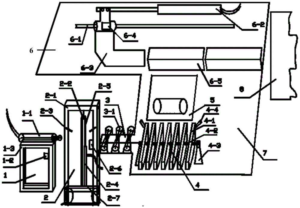
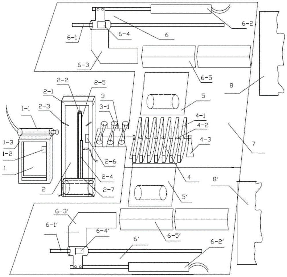
[0024] The present invention is used for cylindrical material automatic lifting feeding device, and this feeding device comprises push rod device 1, lifting device 2, transmission device 3, seesaw device 4, inclined plate 5, pushing device 6, described lifting device 2- A push rod device 1 is provided on one side, a transmission device 3 is provided on the other side of the lifting device 2, a seesaw device 4 is provided on one side of the transmission device 3, an inclined plate 5 is provided on one side of the seesaw device 4, and an inclined plate 5 is provided on one side of the inclined plate 5. A pushing device 6 is provided, and the transmission device 3 , the seesaw device 4 and the pushing device 6 are all arranged on the support plate 7 .

[0025] The push rod device 1 includes a push rod support 1-3, the top of the push rod support 1-3 is fixed with a first telescopic rod 1-1, and the push rod support 1-3 is provided with a first telescopic rod 1-1 for controlling th...

Embodiment 2

[0033] Such as figure 1 , 2 As shown, on the basis of Embodiment 1, both sides of the rocker device 4 are symmetrically provided with inclined plates 5 on the support plate 7, and correspondingly each is equipped with a push device 6. When in use, the lifting groove 2 of the lifting frame 2 -7 is located below the ground, first put the billet to be transported on the ground in front of the lifting device 2, when a billet enters the lifting groove 2-7, the staff starts the switch, the second electromagnetic pneumatic valve 2-6 works, and starts the second telescopic The rod 2-4 raises the lifting groove 2-7 through the pulley block 2-5, and after touching the first sensor 2-3 in the middle and upper part of the lifting frame, the first electromagnetic pneumatic valve 1-2 is started to work, and the first telescopic rod 1-1 Push the billet out of the lifting frame 2, enter the transmission device 3, and drive it to the seesaw device 4, then the first telescopic rod 1-1 returns,...


PUM


Abstract

The invention provides a feeding device for automatically lifting a cylindrical material. The feeding device comprises a pushing rod device, a lifting device, a transmission device, a warping plate device, an inclined plate and a pushing device, wherein one side of the lifting device is provided with the pushing rod device, the other side of the lifting device is provided with the transmission device, one side of the transmission device is provided with the warping plate device, one side of the warping plate device is provided with the inclined plate, one side of the inclined plate is provided with the pushing device, and the transmission device, the warping plate device and the pushing device are all arranged on a supporting plate. The feeding device provided by the invention has the beneficial effects that the operation is simple and convenient, accurate feeding and positioning can be realized, traditional manual feeding is replaced, the operation strength is reduced, the labor cost of 4-6 people can be reduced, and the personal injury risk caused by a weight can be avoided.

Description

technical field [0001] The invention relates to an automatic lifting and feeding device for cylindrical materials, in particular to a feeding device for automatically lifting and transporting heavy objects to a designated position. Background technique [0002] In the field of metal and wood processing, it is often encountered that raw materials such as wood and metal blanks with large quality or large volume need to be processed, and these blanks must be sent into the feed port of the designated equipment. To complete processing or post-processing operations, it is often necessary to handle, lift or haul heavy raw materials or intermediate products. In traditional production, in order to transport these raw materials to be processed into the designated equipment, most of them are transported by forklifts, cranes, transfer vehicles or other tools, or even directly manually. It is time-consuming and labor-intensive, and operation errors can easily cause personal injury, whic...

Claims


Application Information

Patent Timeline
Patent Type & Authority Patents(China)
IPC IPC(8): B65G47/52B65G47/74B65G47/82
Inventor 穆锦辉陈利红石玉志焦洪金
Owner TIANJIN DONGYI MAGNESIUM PROD
Why Eureka
Try Eureka