
Dyeing machine

A dyeing machine and cloth conveying technology, applied in the field of dyeing machines, can solve the problems of low dyeing efficiency, reduce the number of cycles, improve dyeing efficiency and dyeing uniformity

Inactive Publication Date: 2015-03-04
ZHANGJIAGANG HUARI FLANGE
View PDF6 Cites 4 Cited by
  • Summary
  • Abstract
  • Description
  • Claims
  • Application Information

AI Technical Summary

Benefits of technology

This new type of washing machines improves its performance by reducing time needed for dying clothes compared with older types that had better results at one end or even worse.

Problems solved by technology

This patented technical problem addressed by this patents relates to improving the efficient use of traditional machines during finishing operations such as dying or cleaning fabrics made from materials like wools, synthetic fibres (such as polyamide), plastics, rubber, etc., which require repeated steps that result in lower productivity compared with new technologies being developed specifically designed towards improved performance on these types of items.

Method used


Image

  • Dyeing machine

Examples


Embodiment Construction

[0013] The technical scheme of the present invention will be described in further detail below in conjunction with the accompanying drawings and specific embodiments, so that those skilled in the art can better understand the present invention and implement it, but the examples given are not intended to limit the present invention.

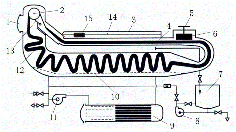
[0014] a dyeing machine such as figure 1 As shown, it includes a cloth delivery pipe 4, a cloth storage tank 10 is arranged at a certain distance from the bottom of the cloth delivery pipe 4, and a rope-like fabric 12 that has been dyed or to be dyed is placed on the cloth storage tank 10. Preferably, the cloth storage Groove 10 is mesh structure, facilitates the seepage of dye liquor. One side of the cloth conveying pipe 4 (ie the left side in the figure) is provided with a sealing door 1 which can seal the cloth conveying pipe 4, and the sealing door 1 is closed during dyeing.

[0015] The cloth conveying pipe 4 is connected to the feeding tank...


PUM


Abstract

The invention discloses a dyeing machine. The dyeing machine comprises a fabric conveying pipe, wherein a fabric storage tank is arranged being a certain distance away from the bottom of the fabric conveying pipe, a sealing door capable of sealing the fabric conveying pipe is arranged at one side of the fabric conveying pipe, the fabric conveying pipe is connected with a charging tank, where a pigment is placed, through a charging pump, and the fabric conveying pipe is connected with a heat exchanger through a circulating pump. The dyeing machine is characterized in that a fabric conveying roller and an overflow spray nozzle are sequentially arranged at one side, close to the sealing door, of the fabric conveying pipe, a compacting block which is used for fixedly compacting a rope-shaped fabric is arranged at the top of one side, far away from the sealing door, of the fabric conveying pipe and moves through an air cylinder, the head and tail ends of the rope-shaped fabric are connected, and the rope-shaped fabric sequentially passes through the compacting block, the overflow spray nozzle, the fabric conveying roller, the fabric storage tank and the compacting block and is subjected to circulated dyeing in the fabric conveying pipe. According to the dyeing machine, the traditional dyeing machine is improved, the times of circulating can be reduced under the condition of obtaining the same dyeing effect, the dyeing efficiency of the dyeing machine is increased, and the dyeing uniformity of the dyeing machine is improved.

Description


Claims


Application Information

Patent Timeline
Owner ZHANGJIAGANG HUARI FLANGE
Learn More