Small-flow control valve

A small flow, control valve technology, applied in the direction of valve lift, valve device, engine components, etc., can solve the problems of large manpower and material resources, easy to wash, poor adjustment accuracy, etc., to solve the problem of small flow adjustment, prolong service life, improve The effect of control precision

Inactive Publication Date: 2015-03-04
WUXI YADI FLUID CONTROL TECH CO LTD
View PDF7 Cites 1 Cited by
  • Summary
  • Abstract
  • Description
  • Claims
  • Application Information

AI Technical Summary

Problems solved by technology

[0002] For the small flow control valves used in the field of micro flow control valves, many domestic manufacturers mostly adopt the structure of the needle-shaped spool. The shape of the needle-shaped spool is corrected to meet the requirements of flow characteristics. The size of the spool is very small, only 1~2mm. Although the small flow valve structure of the needle spool can meet the requirements of the small flow valve, there will be some inherent disadvantages in the actual use process: the needle spool Easy to break, because the size is small, so it is easy to break in actual use, easy to wash, because the size is small, the flow rate of the fluid here is faster, it is easy to cause destructive washing to the needle valve core, and damage the needle Shaped spool, the adjustment accuracy is poor, because the curve of the needle spool is ground through the flow test data and the workers manually grind it out, resulting in differences every time, poor production stability, and unstable adjustment, poor precision, manufacturing The cost is high, because the correction of the small flow spool is done manually. Once the error is manually corrected, the spool will be remade, and in the process of correction, it will consume a lot of manpower and material resources, and it is difficult to meet the purpose of efficient production.

Method used


Image

  • Small-flow control valve
  • Small-flow control valve
  • Small-flow control valve

Examples


Embodiment Construction

[0018] The present invention will be further described below in conjunction with specific drawings and embodiments.

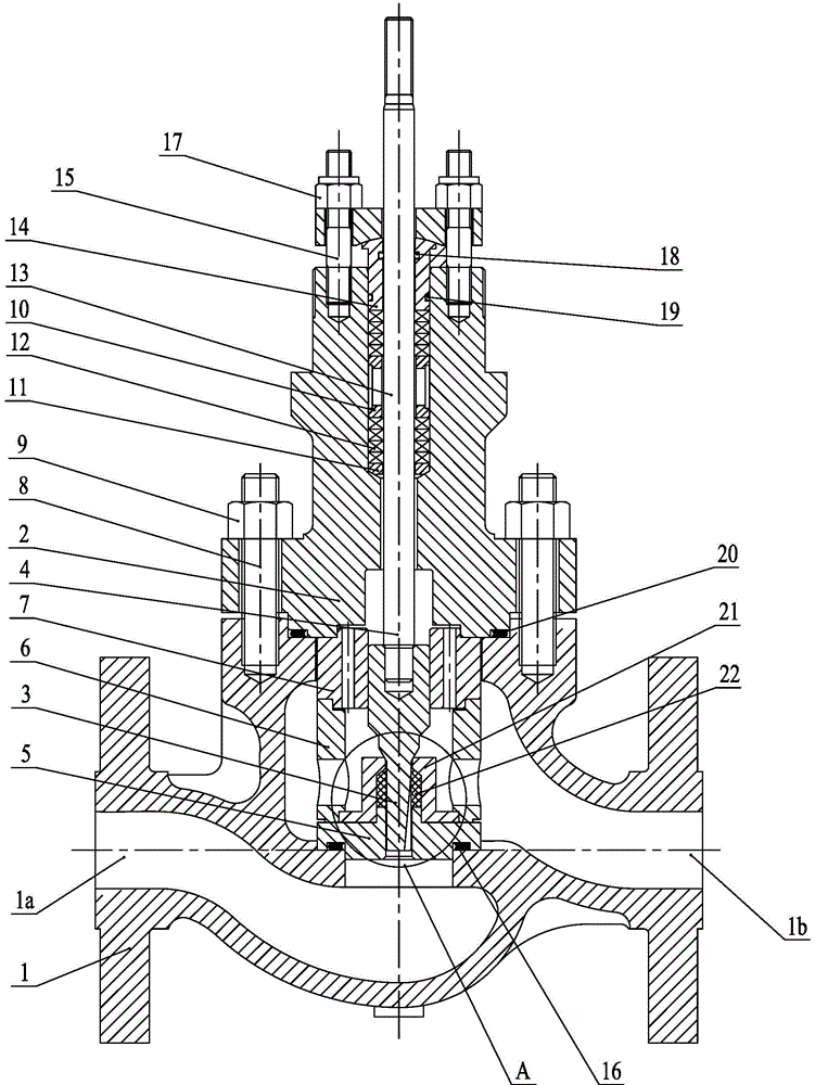
[0019] As shown in the figure: the small flow control valve in the embodiment is mainly composed of a valve body 1, a valve cover 2, a valve core 3, a valve stem 4, a valve seat 5, a spacer 6, a guide sleeve 7, and a first stud 8 , the first hex nut 9, the packing spacer 10, the packing liner 11, the packing 12, the packing gland 13, the packing gland 14, the second stud 15, the valve seat washer 16, the second hex nut 17 , The first O-ring 18, the second O-ring 19, the valve cover gasket 20, the bush seat 21 and the soft sealing bush 22 and so on.

[0020] Such as Figure 1~Figure 4 As shown, the valve body 1 is provided with a valve cavity, the valve seat 5 is installed in the valve cavity, the valve seat 5 is supported by the steps in the valve cavity of the valve body 1, and the contact part between the valve seat 5 and the valve body 1 is in a sealed conn...


PUM


Abstract

The invention relates to a small-flow control valve. A guide sleeve is arranged in a valve cavity and is also arranged on a spacer bush; a bush seat is arranged in an inner hole of the guide sleeve, is also arranged on a valve seat and is pressed by the guide sleeve; a sealing soft bush is arranged in an inner cavity of the bush seat; bush assembly center through holes which axially penetrate through and are communicated are formed in the center of the bush seat and the center of the sealing soft bush; a valve core is assembled in the inner hole of the guide sleeve, an inner hole of the spacer bush, the bush assembly center through holes and the valve seat center hole in a moving manner; the outer circumferential wall of the upper part of the valve core and the inner hole wall of the guide sleeve are in seal sling fit; the outer wall of the lower part of the valve core is in seal sliding fit with the inner walls of the bush assembly center through holes and the inner wall of the center hole of the valve seat; a V-shaped oblique cutting groove along the length direction of the valve core is formed in the outer wall of the lower part of the valve core and has an inclined angle alpha in the length direction and an included angle beta in the direction of the cross section. According to the small-flow control valve disclosed by the invention, the field use requirement can be better met, the miniflow adjustment is realized, the manufacturing cost is reduced, and the control precision is improved.

Description

technical field [0001] The invention relates to a small flow control valve and belongs to the technical field of valve processing and manufacturing. Background technique [0002] For the small flow control valves used in the field of micro flow control valves, many domestic manufacturers mostly adopt the structure of the needle-shaped spool. The shape of the needle-shaped spool is corrected to meet the requirements of flow characteristics. The size of the spool is very small, only 1~2mm. Although the small flow valve structure of the needle spool can meet the requirements of the small flow valve, there will be some inherent disadvantages in the actual use process: the needle spool Easy to break, because the size is small, so it is easy to break in actual use, easy to wash, because the size is small, the flow rate of the fluid here is faster, it is easy to cause destructive washing to the needle valve core, and damage the needle Shaped spool, the adjustment accuracy is poor,...

Claims


Application Information

Patent Timeline
Patent Type & Authority Applications(China)
IPC IPC(8): F16K1/00F16K1/36F16K1/32
CPCF16K1/00F16K1/32F16K1/36
Inventor 管瑞缪栖涯
Owner WUXI YADI FLUID CONTROL TECH CO LTD
Why Eureka
Try Eureka