Fault detection and communication positioning method for transmission line

A technology of fault detection and positioning method, applied in the field of communication positioning, can solve the problems of inability to directly measure distance, fail to reflect fault branches, and high equipment cost, and achieve the effect of improving anti-interference ability, compact structure and high degree of automation

Active Publication Date: 2015-03-04
NANYANG POWER SUPPLY COMPANY OF STATE GRID HENAN ELECTRIC POWER
View PDF6 Cites 4 Cited by
  • Summary
  • Abstract
  • Description
  • Claims
  • Application Information

AI Technical Summary

Problems solved by technology

[0002] Transmission line fault location is an important technology to quickly find the fault point when the transmission line fails. At present, there are three main methods for transmission line fault location: short-circuit distance measurement method, fault indicator method and hand-held detector line inspection method, short-circuit detection method The distance method is to determine the location of the short-circuit point by measuring the line impedance from the short-circuit point to the measurement point and estimating the length of the line from the short-circuit point to the measurement point. This method requires high equipment cost, and cannot reflect the fault branch, and cannot directly measure The fault indicator method is to install a fault indicator along the transmission line. When the line is faulty, there is a fault characteristic current flowing on the fault section line, and by detecting the fault characteristic current , the fault indicator on the fault line has a mechanical flip or light indication. The main problem of the fault indicator method is that the inspectors must patrol the indicator along the fault line, and the workload is large and the time is long; the hand-held detector line inspection method follows the Same problem as above

Method used


Image

  • Fault detection and communication positioning method for transmission line
  • Fault detection and communication positioning method for transmission line
  • Fault detection and communication positioning method for transmission line

Examples


Embodiment Construction

[0015] The following will clearly and completely describe the technical solutions in the embodiments of the present invention with reference to the accompanying drawings in the embodiments of the present invention. Obviously, the described embodiments are only some, not all, embodiments of the present invention. Based on the embodiments of the present invention, all other embodiments obtained by persons of ordinary skill in the art without making creative efforts belong to the protection scope of the present invention.

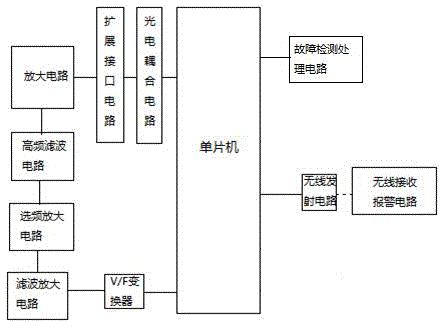
[0016] see Figure 1~4 , in an embodiment of the present invention, a transmission line fault detection communication positioning method, including a single-chip microcomputer, a photoelectric coupling circuit, an expansion interface circuit, an amplification circuit, a high-frequency filter circuit and a wireless transmission circuit, and the single-chip microcomputer is respectively connected to the photoelectric coupling circuit and the wireless transmission...


PUM


Abstract

The invention discloses a fault detection and communication positioning method for a transmission line. The method involves a single-chip microcomputer, a photoelectric coupling circuit, an expansion interface circuit, an amplifying circuit, a high-frequency filter circuit and a wireless emitting circuit. According to the method, the AT89C51 single-chip microcomputer and a plurality of integrated circuit chips form a mini system, and all the circuits of the mini system are integrated to a printed circuit board; therefore, the structure is compact, the size is small, and the process is simple; automation degree and working performance are increased and improved by being compared with the traditional digital circuit; the rich software functions of the computer are utilized; the data are sampled, memorized and processed, to reasonably realize automatic and intelligent data scanning of each branch of a DC system; the number and polarity of each ground branch can be positioned; in addition, an operator can be reminded by a wireless alarming manner to timely treat the ground fault.

Description

technical field [0001] The invention relates to a communication positioning method, in particular to a transmission line fault detection communication positioning method. Background technique [0002] Transmission line fault location is an important technology to quickly find the fault point when the transmission line fails. At present, there are three main methods for transmission line fault location: short-circuit distance measurement method, fault indicator method and hand-held detector line inspection method, short-circuit detection method The distance method is to determine the location of the short-circuit point by measuring the line impedance from the short-circuit point to the measurement point and estimating the length of the line from the short-circuit point to the measurement point. This method requires high equipment cost, and cannot reflect the fault branch, and cannot directly measure The fault indicator method is to install a fault indicator along the transmis...

Claims


Application Information

Patent Timeline
Patent Type & Authority Applications(China)
IPC IPC(8): G01R31/08
Inventor 张治国张鹏飞
Owner NANYANG POWER SUPPLY COMPANY OF STATE GRID HENAN ELECTRIC POWER
Why Eureka
Try Eureka