Power supply unit

A power supply device and voltage technology, applied in the field of electric power, can solve the problems of mismatch between the power supply voltage and the rated voltage of the electric energy meter, lack of power supply, etc., and achieve the effects of ensuring safety, saving costs, and controlling the operation process.

Active Publication Date: 2015-03-04
成都博高信息技术股份有限公司
View PDF3 Cites 0 Cited by
  • Summary
  • Abstract
  • Description
  • Claims
  • Application Information

AI Technical Summary

Problems solved by technology

[0004] The purpose of the present invention is to provide a power supply device, which is used to solve the problems of lack of power supply at the work site and the mismatch between the power supply voltage and the rated voltage of the electric energy meter

Method used


Image

  • Power supply unit
  • Power supply unit
  • Power supply unit

Examples


Embodiment 1

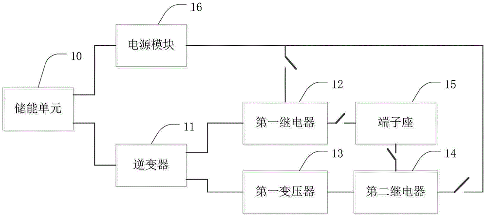
[0039] figure 1 It is a structural diagram of a power supply device provided by the present invention. The power supply includes:

[0040] The energy storage unit 10 is used for storing electric energy;

[0041] The energy storage unit 10 stores electric energy through an external power source, and provides electric energy for other components of the power supply device.

[0042] An inverter 11 connected to the first output end of the energy storage unit 10, configured to convert the voltage output by the energy storage unit 10 into a first voltage;

[0043] Since the output voltage of the energy storage unit 10 is usually too small to meet the rated voltage of most electric energy meters, the inverter 11 is required to convert the voltage of the first output terminal of the energy storage unit 10 . By connecting the inverter 11 to the first output terminal of the energy storage unit 10, the inverter 11 can convert the relatively small voltage output by the energy storage u...

Embodiment 2

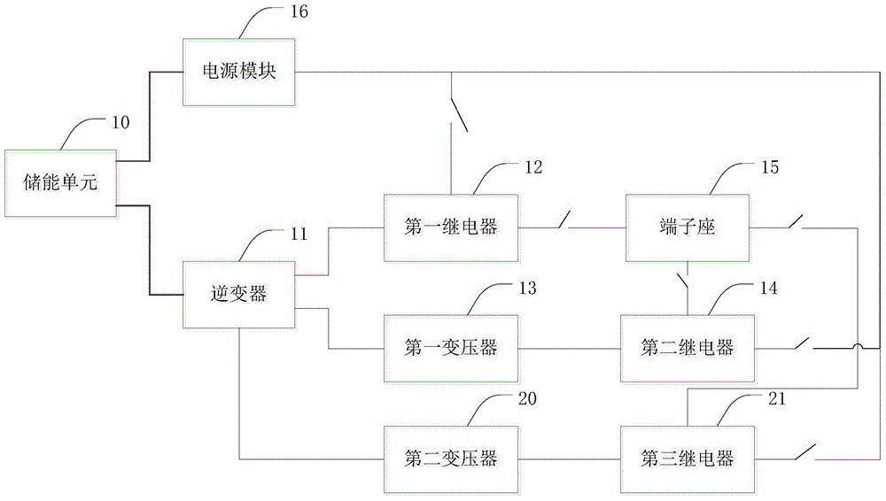
[0061] figure 2 It is a structural diagram of another power supply device provided by the present invention. On the basis of Embodiment 1, the power supply device also includes:

[0062] A second transformer 20 connected to the third output terminal of the inverter 11, for converting the first voltage into a third voltage;

[0063] And a third relay 21 connected to the output end of the second transformer 20;

[0064] Wherein, the output end of the second transformer 20 is connected to the normally open contact of the third relay 21, for outputting the third voltage to the normally open contact of the third relay 21; The normally open contacts of the three relays 21 are connected to the terminal block 15; the switch of the third relay 21 is connected to the first output end of the power module 16, for controlling the third relay in the closed state The normally open contact of 21 is closed.

[0065] At the work site, different electric energy meters require different rate...

Embodiment 3

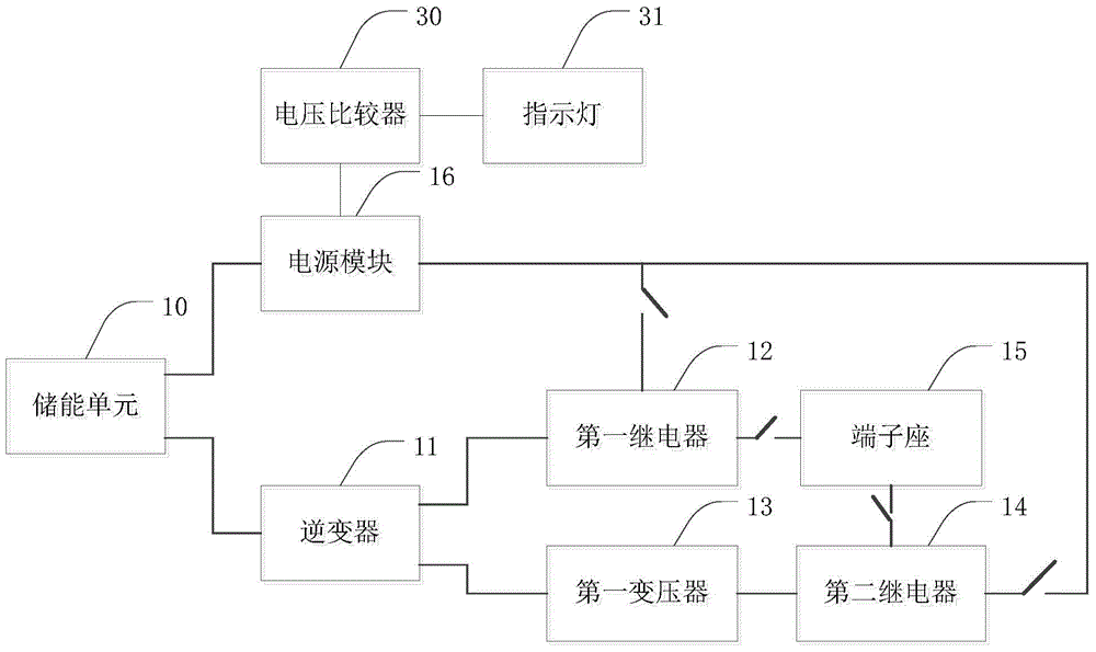
[0069] image 3 It is a structural diagram of another power supply device provided by the present invention. The power supply also includes:

[0070] A voltage comparator 30 connected to the second output terminal of the power module, for comparing the driving voltage and the reference voltage;

[0071] And an indicator light 31 connected to the voltage comparator 30 is used to prompt when the comparison result of the voltage comparator 30 is abnormal.

[0072] The energy storage of the energy storage unit 10 is limited. During use, the output voltage may no longer be the rated output voltage, which will lead to errors in the first voltage output by the inverter 11 and the driving voltage output by the power module 16, affecting the power supply. normal operation of the device. Therefore, in order to be able to control the working conditions of the power supply device in time, a voltage comparator 30 is connected to the second output terminal of the power module 16 and an i...


PUM


Abstract

The invention discloses a power supply unit. The power supply unit comprises an energy storage unit, an inverter connected to the first output end of the energy storage unit; a first relay connected to the first output end of the inverter; a first transformer connected to the second output end of the inverter; a second relay connected to the output end of the first transformer; a terminal seat connected to the normally open contact of the first relay and the normally open contact of the second relay; a power supply module connected to the second output end of the energy storage unit; the switch of the first relay is connected to the first output end of the power supply module and used for controlling the normally open contact of the first relay for closing under the closed state; the switch of the second relay is connected to the first output end of the power supply module and used for controlling the normally open contact of the second relay for closing under the closed state. Therefore, the power using difficulty problem of the electric energy meter for the job site is solved and the work voltage is optional.

Description

technical field [0001] The invention relates to the technical field of electric power, in particular to a power supply device. Background technique [0002] In order to more effectively and intuitively obtain the working conditions of the work site, for example, the site of power consumption, it is usually necessary to go to the work site for on-the-spot measurement and collection. Sometimes there are many types of data that need to be measured and collected, including pictures, real-time power consumption data, etc., and sometimes it is necessary to send the collected data at the work site remotely. Therefore, different energy meters are used at the job site. However, due to the limitation of site conditions, there may be situations where there is not enough power supply or the power supply is out of power or the power supply voltage does not match the rated voltage of the energy meter; there may also be a mismatch between the power socket of the energy meter and the power...

Claims


Application Information

Patent Timeline
Patent Type & Authority Applications(China)
IPC IPC(8): H02J7/34H02M1/10
CPCH02J7/34
Inventor 何世刚肖俭伟张保平
Owner 成都博高信息技术股份有限公司
Why Eureka
Try Eureka