
Turbine

An impeller and impeller technology, applied in the direction of engines, mechanical equipment, wind turbines, etc., can solve the problems of energy waste, low utilization of hydraulic and wind resources, etc.

Inactive Publication Date: 2008-04-23
祝安心
View PDF5 Cites 0 Cited by
  • Summary
  • Abstract
  • Description
  • Claims
  • Application Information

AI Technical Summary

Problems solved by technology

Existing impellers that use water power and wind power to generate electricity have a low utilization rate of water power and wind power resources, and a large amount of energy is wasted

Method used


Image

  • Turbine
  • Turbine

Examples


Embodiment Construction

[0023] specific implementation

[0024] Below in conjunction with accompanying drawing and embodiment the present invention is further described:

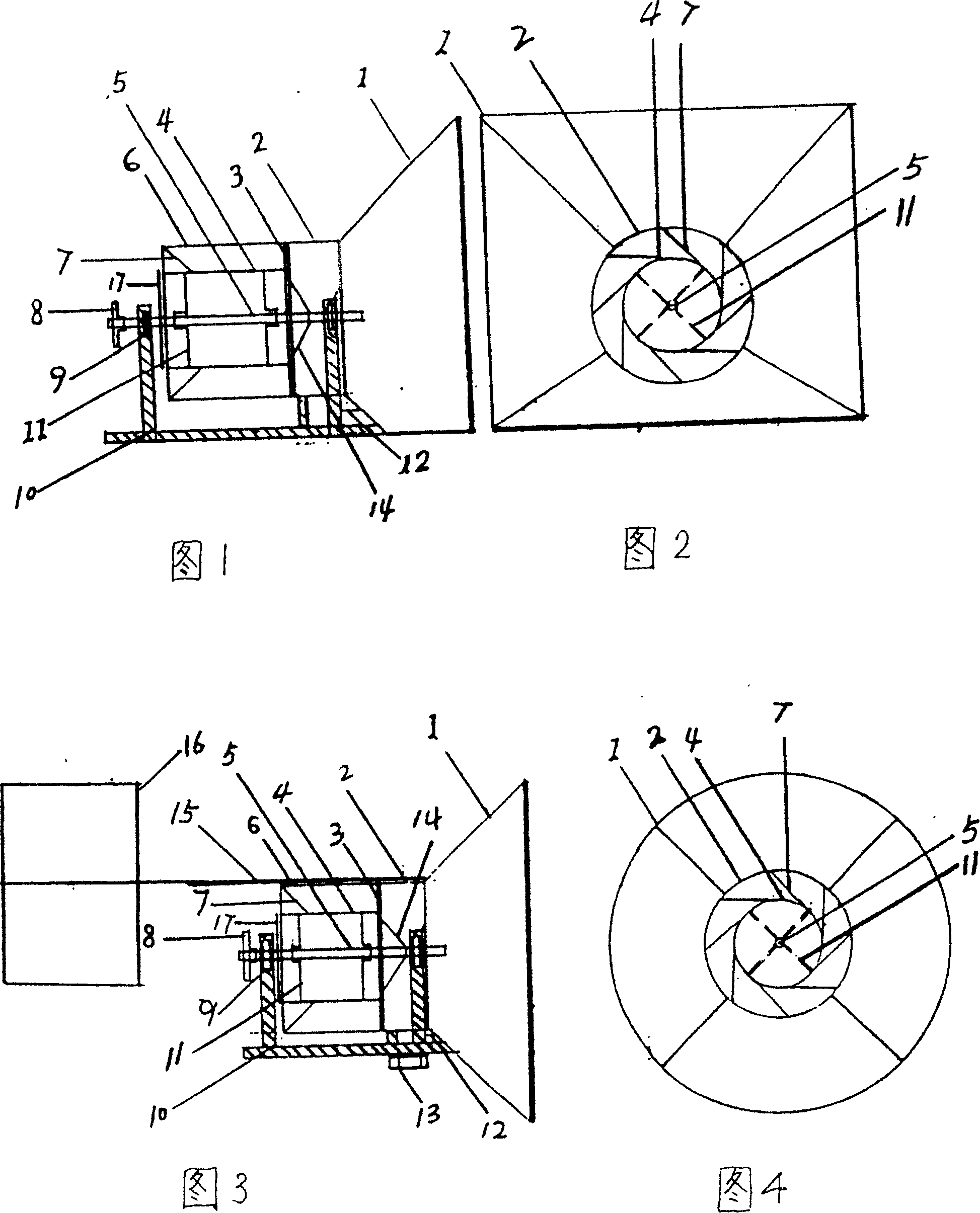
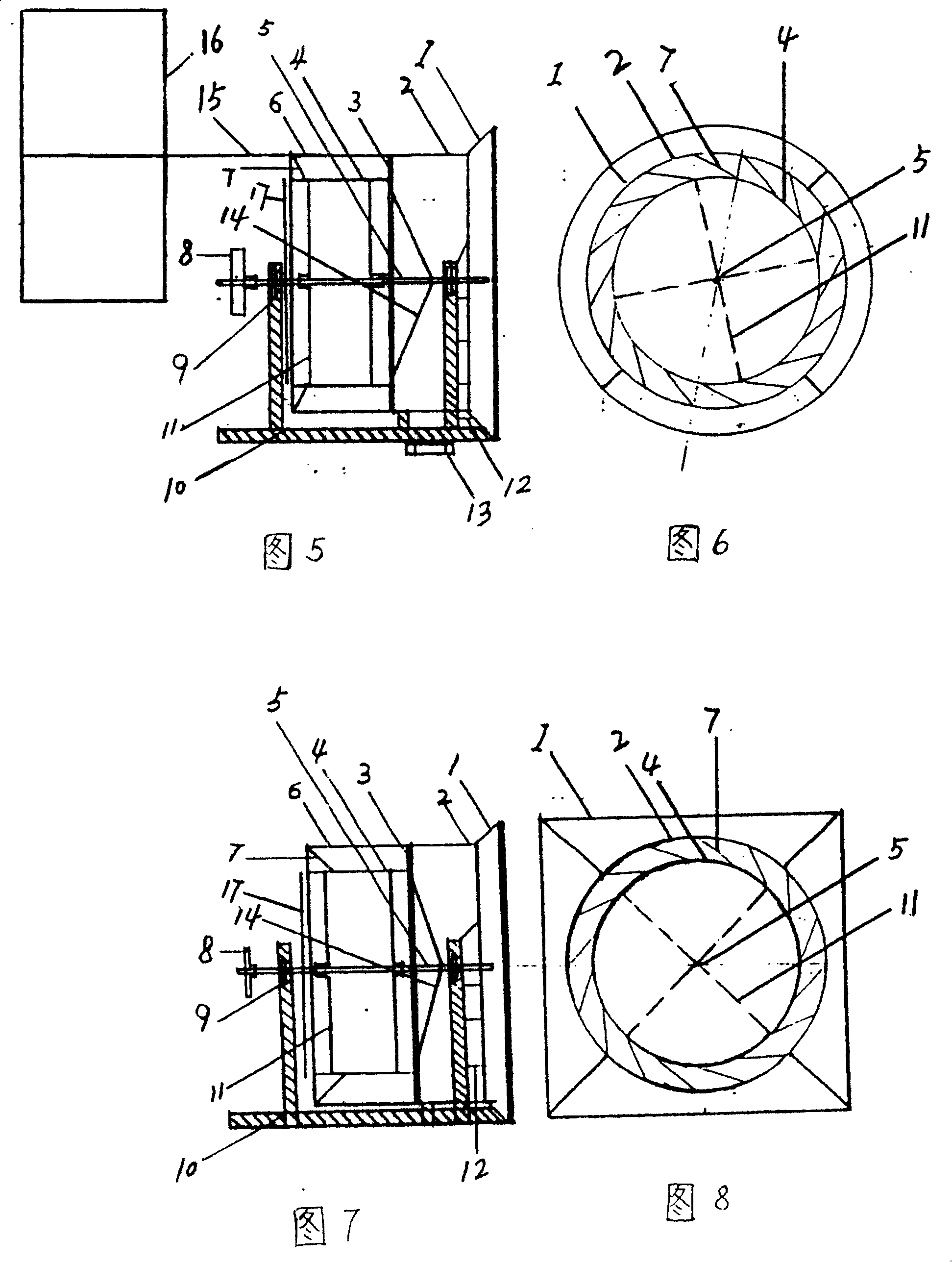
[0025] In the examples shown in Figures 1, 3, 5, and 7, the air inlet bucket 1 is connected to the connecting cylinder 2, the outer cylinder 6 is connected to the connecting cylinder 2 through a joint 3 (socket socket), and the blades 7 are connected to the outer cylinder 6. The inner diameter is connected, the other end of the blade 7 is connected to the outer diameter of the inner cylinder 4, the tension rib 11 is connected to the inner diameter of the inner cylinder 4, the other end of the tension rib 11 is connected to the axis 5, the outlet of the air guide cylinder 14 is connected to the inlet of the inner cylinder 4, and the air guide The inlet of the cylinder 14 is connected with the axis 5, the cover plate 17 is connected with the outlet of the inner cylinder 4, the bearing 9 is connected with the axis 5, the base 10 is co...


PUM


Abstract

A blade-wheel machine using water power and wind power to generate electric energy is composed of external cylinder, internal cylinder, the flow guiding barrel at the front end of internal cylinder for increasing speed and energy of fluid, blade wheel with blades between internal and external cyliners, machine base, and bearings.

Description

technical field [0001] The present invention relates to a kind of mechanical device that utilizes running water and wind power to generate electricity—the impeller machine. Background technique [0002] At present, in the existing turbines that use hydraulic power and wind power to generate electricity, the entire blade is in contact with the fluid from the root of the blade to the tip of the blade. When generating electricity, a strong fluid is required to impact the blades. To use such a turbine to generate electricity, it must be under good conditions. In some areas, building a dam, raising the water level, and turning the blades to generate electricity due to the impulsive force or pressure of the upstream reservoir area has invested a lot of manpower and material resources and occupied a large amount of planting area. Existing turbines that utilize water power and wind power to generate electricity have relatively low utilization rates of water power and wind power reso...

Claims


Application Information

Patent Timeline
Patent Type & Authority Patents(China)
IPC IPC(8): F03B3/04F03D1/06
CPCY02E10/223Y02E10/721Y02E10/20Y02E10/72
Inventor 祝安心
Owner 祝安心
Learn More