Supercharge Your Innovation With Domain-Expert AI Agents!

Half-bridge MMC (Modular Multilevel Converter) sub-module voltage control method

A modular multi-level, sub-module voltage technology, applied in the direction of converting AC power input to DC power output, electrical components, output power conversion devices, etc., can solve damaged sub-modules, DC capacitor voltage imbalance, DC capacitors voltage distortion and other problems, to achieve the effect of improving the level of safe operation, prolonging the service life and improving the quality

Active Publication Date: 2015-03-04
NORTH CHINA ELECTRIC POWER UNIV (BAODING)
View PDF3 Cites 3 Cited by
  • Summary
  • Abstract
  • Description
  • Claims
  • Application Information

AI Technical Summary

Problems solved by technology

[0004] Due to the large number of sub-modules of each bridge arm in each phase of the half-bridge MMC, the switching actions of each sub-module may be inconsistent, resulting in an unbalanced DC capacitor voltage of the sub-modules, which increases the distortion of the output voltage waveform of the half-bridge MMC and affects the half-bridge. The quality of the MMC output voltage waveform, if the deviation is serious, the sub-module will be damaged
[0005] In addition, when an asymmetrical fault occurs in the power grid, it will further cause DC capacitor voltage distortion and affect the safe operation level of the entire device.

Method used


Image

  • Half-bridge MMC (Modular Multilevel Converter) sub-module voltage control method
  • Half-bridge MMC (Modular Multilevel Converter) sub-module voltage control method
  • Half-bridge MMC (Modular Multilevel Converter) sub-module voltage control method

Examples


Embodiment Construction

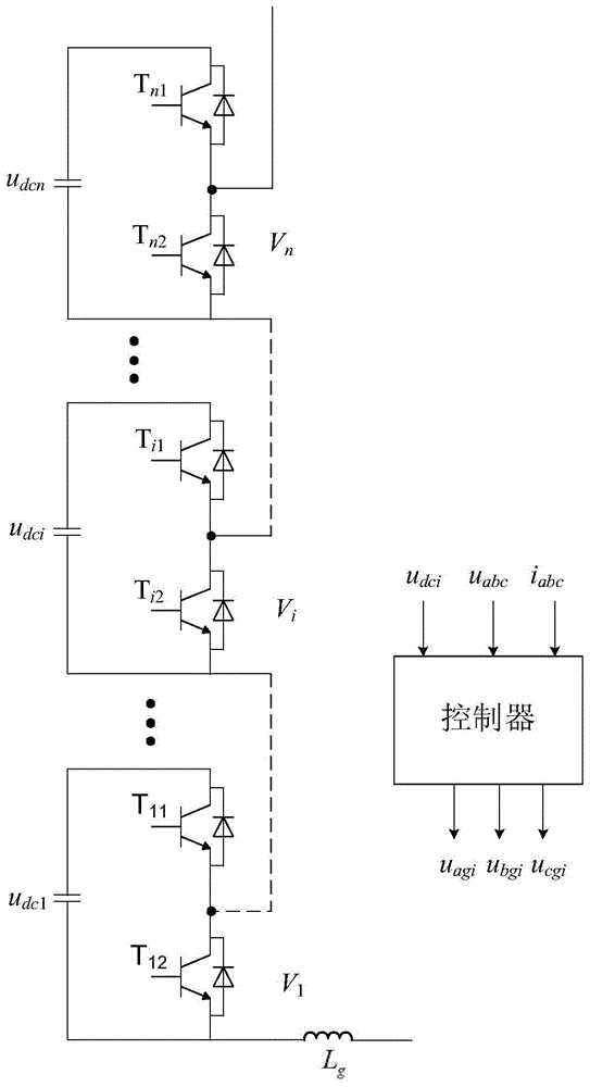
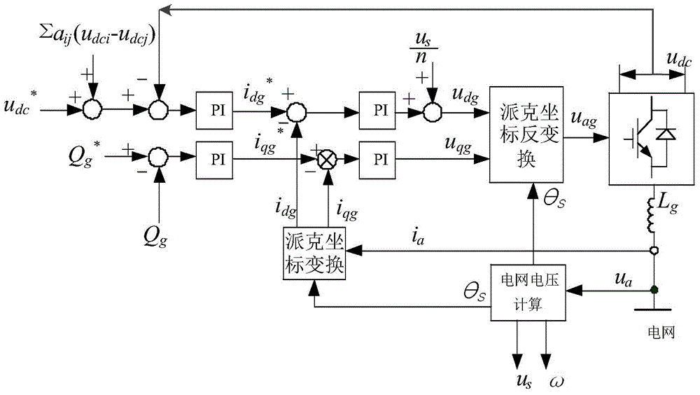
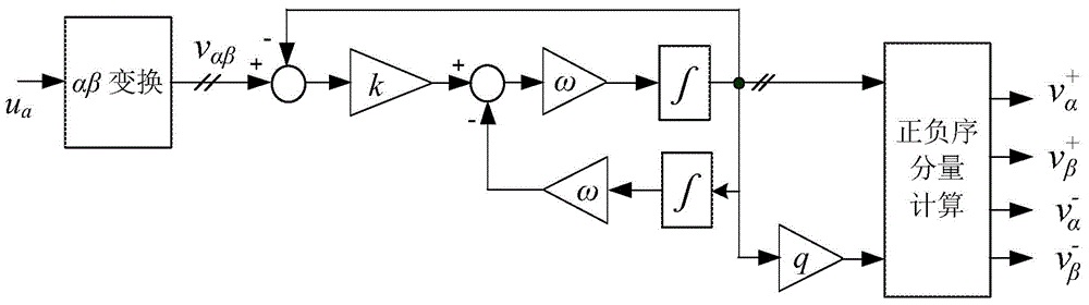
[0028] The present invention will be described in detail below in conjunction with the accompanying drawings.

[0029] Detailed exemplary embodiments are disclosed below. However, specific structural and functional details disclosed herein are merely for purposes of describing example embodiments.

[0030] It should be understood, however, that the invention is not limited to the particular exemplary embodiments disclosed, but covers all modifications, equivalents, and alternatives falling within the scope of the disclosure. Throughout the description of the figures, the same reference numerals denote the same elements.

[0031] Also, it should be understood that as used herein, the term "and / or" includes any and all combinations of one or more of the associated listed items. Also it will be understood that when a component or unit is referred to as being “connected” or “coupled” to another component or unit, it can be directly connected or coupled to the other component or ...


PUM


Abstract

A half-bridge MMC (Modular Multilevel Converter) sub-module voltage control method comprises step A, presetting a half-bridge MMC direct current voltage given value the formula and a reactive power given value the formula; step B, measuring the direct current voltage udc and every phase alternating current voltage ua and current ia, obtaining a voltage amplitude value us and the phase position from the ua and performing the Park transformation on the ia and the phase position to obtain idg and iqg; step C, setting a weight coefficient aij, adding a formula value and the formula together and enabling the result to be minus the udc, enabling the result to be minus the idg through the output after the outer ring proportional integral link and adding the difference value and the us / n together after the inner ring proportional integral link to obtain udgi, wherein udci and udcj are the direct current capacitance voltages of an i sub-module and a j sub-module in n sub-modules respectively; step D, performing comparison on the difference of the measured reactive power and the formula and the iqg through the output after the outer ring proportional integral link and obtaining uqgi through the difference value after the inner ring proportional integral link; Step E, performing the Park inverse transformation on the udgi and the uqji to obtain the control quantity uagi of the i sub-module and controlling a switch of the i sub-module according to the control quantity.

Description

technical field [0001] The invention relates to the field of power electronic equipment, in particular to a control technology for each power switching device in the power electronic equipment. Background technique [0002] With the rapid development of power electronics technology, the withstand voltage and power level of a single power switching device have been greatly improved, and the application of various high-power switching devices is becoming more and more extensive. However, in many high-voltage and high-power applications, the traditional two-level and three-level voltage source converter topologies can no longer meet the requirements of higher voltage and power levels. Under the premise that there is no essential breakthrough in power switching devices, multilevel converters are undoubtedly the best choice to solve high-voltage and high-power conversion. In order to increase the capacity of power electronic devices and improve their performance, people have stu...

Claims


Application Information

Patent Timeline
Patent Type & Authority Applications(China)
IPC IPC(8): H02M7/483
CPCH02M7/483H02M1/0003H02M7/4835
Inventor 李云昭徐永海
Owner NORTH CHINA ELECTRIC POWER UNIV (BAODING)
Features
  • R&D
  • Intellectual Property
  • Life Sciences
  • Materials
  • Tech Scout
  • Unparalleled Data Quality
  • Higher Quality Content
  • 60% Fewer Hallucinations
Learn More