Cascaded welding machine power supply topology

A topology and electric welding machine technology, applied in arc welding equipment, welding equipment, welding accessories, etc., can solve the problems of uncertain cable connection length, parameter offset, high cost of speed regulation, etc., to improve overall efficiency and reliability , reduce volume and cost, control precise and reliable effects

Active Publication Date: 2016-02-03
东莞市英豪智能科技有限公司
View PDF8 Cites 0 Cited by
  • Summary
  • Abstract
  • Description
  • Claims
  • Application Information

AI Technical Summary

Problems solved by technology

[0003] Based on the above structure, the current electric welding machine power supply structure has the following defects: (1) Since the length of the cable connection between the wire feeder and the electric welding machine host is uncertain (general manufacturers can only achieve 50 meters), different wire lengths The influence on the control accuracy of the wire feeder motor is inconsistent
(2) Since the analog setting of the wire feeder is sent to the welding machine host through a long cable, the longer the cable length, the easier it is to be interfered
(3) The analog given potentiometer on the wire feeder and the control circuit of the motor are analog circuits that are easily polluted by the environment, resulting in parameter deviation or even failure
(5) The power supply of the wire feeder motor through the thyristor + power frequency transformer scheme is high in cost and large in size, and the power frequency transformer has no-load loss, which is easy to heat up and affect the life of the transformer and waste electric energy
(6) The main heat dissipation fan of the welding machine host adopts multi-stage or linear fans to adjust the speed and the cost is high, so AC fans are generally used, which cannot adjust the speed and still run at full speed under low load, which is not conducive to energy saving and environmental protection

Method used


Image

  • Cascaded welding machine power supply topology
  • Cascaded welding machine power supply topology
  • Cascaded welding machine power supply topology

Examples


Embodiment Construction

[0038] In the following, the present invention will be further described in conjunction with the drawings and specific embodiments.

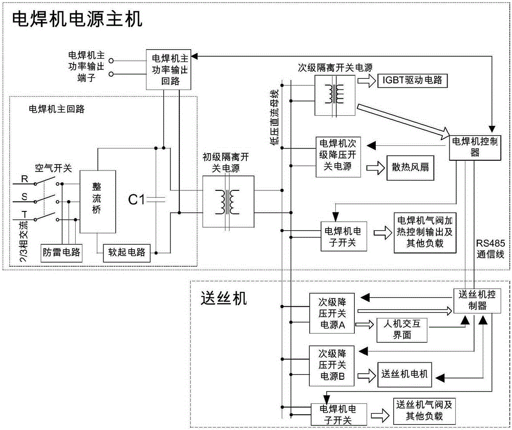
[0039] Such as figure 1 As shown, a cascaded welding machine power topology, which includes a welding machine power host and a wire feeder.

[0040] The welding machine power host includes a welding machine main circuit, a primary isolating switching power supply, a secondary isolating switching power supply, an electric welding machine electronic switch, a welding machine controller and a secondary step-down switching power supply of the welding machine (BUCK switching power supply can be used). The main circuit of the electric welding machine includes a rectifier bridge, a filter capacitor C1, a lightning protection circuit and a soft starting circuit.

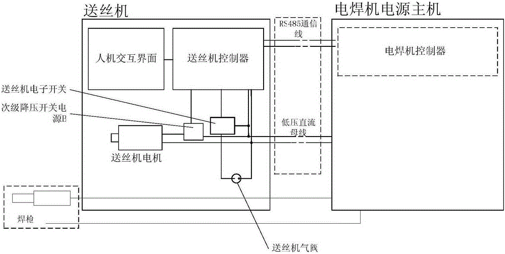
[0041] The wire feeder includes a secondary step-down switching power supply A, a secondary step-down switching power supply B, a wire feeder controller, an electronic switch for the wire fe...


PUM


Abstract

The invention relates to a cascaded electric welding machine power supply topological structure. The cascaded electric welding machine power supply topological structure comprises an electric welding machine power supply host and a wire feeding machine; the electric welding machine power supply host comprises an electric welding machine main loop, a primary isolating switch power supply, a secondary isolating switch power supply, an electric welding machine controller and an electric welding machine secondary step-down switch power supply; the wire feeding machine comprises a secondary step-down switch power supply A, a secondary step-down switch power supply B, a wire feeding machine controller and a human-computer interaction interface which is used for inputting a control instruction to the wire feeding machine controller; the electric welding machine controller is connected with the wire feeding machine controller through a communication line. The cascaded electric welding machine power supply topological structure has the advantages of being small in size, low in cost, low in standby loss, high in comprehensive efficiency and high in reliability.

Description

technical field [0001] The invention relates to the electric welding machine technology, in particular to the power supply technology of the electric welding machine with an external wire feeder. Background technique [0002] Such as image 3 As shown, the current electric welding machine with a wire feeder and an external wire feeder generally consists of a welding machine power host and a wire feeder. The welding machine power host is connected through the wire feeder control cable. The welding machine power host is equipped with a main control panel integrated with all control buttons, and the wire feeder is equipped with a simple control panel that only integrates current, voltage, wire feeding and welding buttons. panel. The function of the wire feeder is mainly to install the welding wire and adjust some welding parameters. Compared with the main machine of the electric welding machine, the wire feeder is light in weight and small in size. It is generally placed near ...

Claims


Application Information

Patent Timeline
Patent Type & Authority Patents(China)
IPC IPC(8): B23K9/10B23K9/12B23K9/32
CPCB23K9/1043B23K9/1336
Inventor 郭智峰
Owner 东莞市英豪智能科技有限公司
Why Eureka
Try Eureka