A friction stir lap welding method for reducing the size of interface defects

A friction stir and interface defect technology, applied in welding equipment, non-electric welding equipment, metal processing equipment, etc., can solve the problems of reducing the mechanical properties of joints, reducing the effective bearing thickness and effective lap width of joints, and increasing the effective lap width. The effect of reducing the joint area, reducing the cold lap defect, and reducing the bending deformation

Inactive Publication Date: 2016-03-23
HARBIN INST OF TECH
View PDF7 Cites 0 Cited by
  • Summary
  • Abstract
  • Description
  • Claims
  • Application Information

AI Technical Summary

Problems solved by technology

[0004] In order to solve the problem that two kinds of interface defects in the existing friction stir lap welding joint reduce the effective load-bearing thickness and effective lap width of the joint, and reduce the mechanical properties of the joint, a kind of friction stir lap welding that reduces the size of the interface defect is proposed Stirring head and its welding method

Method used


Image

  • A friction stir lap welding method for reducing the size of interface defects
  • A friction stir lap welding method for reducing the size of interface defects

Examples


specific Embodiment approach 1

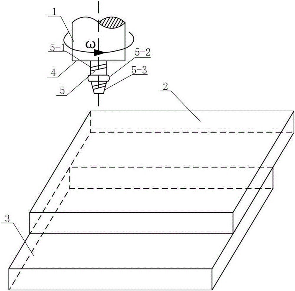
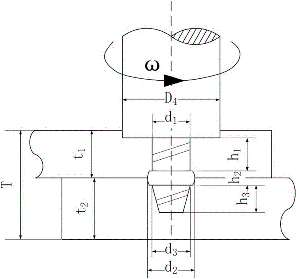
[0018] Specific Embodiment 1: In this embodiment, the stirring head 1 for friction stir lap welding that reduces the size of the interface defect is composed of a shaft shoulder 4 and a stirring pin 5. The cylinder 5-1, the middle convex circle 5-2 and the lower round platform 5-3 are composed, one end of the upper cylinder 5-1 is fixed on the lower end surface of the shoulder 4, the other end of the upper cylinder 5-1 is connected with the middle convex circle 5 -2 connection, the lower end surface of the middle convex circle 5-2 is connected to the bottom surface of the lower round platform 5-3, and the diameter d of the upper cylinder 5-1 1 and the bottom surface diameter d of the lower round platform 5-3 3 equal, the diameter d of the upper cylinder 5-1 1 Smaller than the diameter d of the central convex circle 5-2 2 , and there are right-hand threads on the outer surfaces of the upper cylinder 5-1 and the lower round table 5-3.

specific Embodiment approach 2

[0019] Specific embodiment two: In this embodiment, the friction stir lap welding method for reducing the size of the interface defect is implemented according to the following steps:

[0020] 1. Determine the size of the stirring head: according to the thickness t of the first workpiece 2 to be welded 1 and the thickness t of the second workpiece 3 to be welded 2 And the total thickness T obtained by adding the thicknesses of the first workpiece 2 and the second workpiece 3 to be welded determines the diameter D of the shoulder 4 4 , the diameter d of the upper cylinder 5-1 of the stirring needle 1 , The diameter d of the bottom surface of the lower round table 5-3 3 , the diameter d of the convex circle 5-2 in the middle 2 , the diameter D of the shoulder 4 4 3 to 5 times the total thickness T, the diameter d of the upper cylinder 5-1 of the stirring needle 1 and the bottom surface diameter d of the lower round platform 5-3 3 1 to 2 times the total thickness T, the dia...

specific Embodiment approach 3

[0026] Specific embodiment three: the difference between this embodiment and specific embodiment two is the diameter D of the shoulder 4 in step one 4 4 times the total thickness T, the diameter d of the upper cylinder 5-1 of the stirring needle 1 and the bottom surface diameter d of the lower round platform 5-3 3 1.5 times the total thickness T, the diameter d of the convex circle 5-2 in the middle 2 For the upper cylinder 5-1 diameter d 1 1.4 times. Other steps and parameters are the same as in the second embodiment.

[0027] The dimensions of the stirring head in this embodiment can ensure the stability of the weld seam formation.


PUM


Abstract

The invention discloses a stirring head for friction stir overlap welding for reducing the size of an interface defect and a welding method thereof, relates to the stirring head for the friction stir overlap welding and the welding method thereof, and aims to solve the problem that the effective bearing capacity, the effective overlap width and the mechanical property of a joint are effectively reduced by an advancing side Hook defect and a retreating side cold overlap defect in the existing friction stir overlap welding joint. The stirring head for the friction stir overlap welding consists of a shaft shoulder and a stirring pin, wherein the stirring pin is formed by connecting an upper cylinder, a middle dome and a lower circular truncated cone in sequence. The welding method comprises the following steps: I, determining the size of the stirring head; II, determining the length of the stirring pin; III, fixing a welded workpiece; IV, pressing the middle dome of the stirring pin to the overlap interface of two welded workpieces; V, performing friction stir welding. In the welding process, the original overlap interface is stirred by using the middle dome, so that the size of the interface defect is effectively reduced, and the overlap area is also effectively increased to improve the mechanical property of the joint.

Description

technical field [0001] The invention belongs to the field of welding technology, and in particular relates to a stirring head for friction stir lap welding and a welding method thereof. Background technique [0002] Friction stir welding is a new type of solid-phase joining technology developed by the British Welding Institute in 1991. It has the advantages of small deformation of the welded joint and automatic welding process, and overcomes the defects of traditional fusion welding such as pores and slag inclusions. It can obtain Defect-free high-quality joints. As one of the main joint forms, lap joints are widely used in welding. However, in the friction stir lap welding joint, the original lap interface on both sides of the weld nugget is bent upward or downward due to the plastic flow of the weld material, which mainly includes the Hook defect on the advancing side and the "cold lap" on the retreating side. There are two kinds of interface defects such as contact defe...

Claims


Application Information

Patent Timeline
Patent Type & Authority Patents(China)
IPC IPC(8): B23K20/12
CPCB23K20/1255
Inventor 胡琰莹刘会杰赵运强林喆刘向前窦超
Owner HARBIN INST OF TECH
Why Eureka
Try Eureka