

Laser welding method, pump for supplying high-pressure fuel, and fuel injection valve
A laser welding and laser technology, which is applied in laser welding equipment, welding equipment, transportation and packaging, etc., can solve the problems of effective welding length change, excessive heat input, etc., and achieve longer effective welding length, enlarged welding width, and improved Effect of Target Position Margin
- Summary
- Abstract
- Description
- Claims
- Application Information
AI Technical Summary
Problems solved by technology
Method used
Image

Examples
Embodiment 1
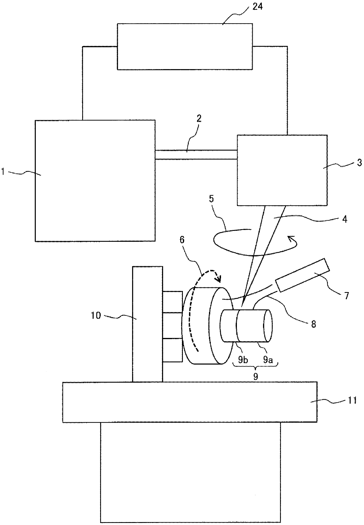
[0043] figure 1 It is a schematic diagram of the laser welding apparatus of Example 1.
[0044] exist figure 1 Among them, 1 indicates the laser oscillator, 2 indicates the optical fiber for the laser, 3 indicates the galvanometer scanner, 4 indicates the laser, 5 indicates the rotation direction of the laser, and 6 indicates the rotation direction of the object to be welded (moving direction of the welded part) , 7 denotes a shielding gas nozzle, 8 denotes a shielding gas, 9 denotes an object to be welded, 10 denotes a rotating spindle, 11 denotes a processing table, and 24 denotes a control device.
[0045] In this embodiment, the welding object 9 is a fuel pump component, and the material is 304 stainless steel. In addition, laser light 4 is a disk laser with a wavelength of about 1030 nm. The scanning track of the laser 4 is a circle. Laser 4 tilts 25° for construction. The protective gas 8 is nitrogen.
[0046] Laser light 4 generated by laser oscillator 1 reaches g...
Embodiment 2
[0065] refer to Figure 4 ~ Figure 6B , Embodiment 2 of the present invention will be described. In each figure, the same reference numerals as in the first embodiment are attached to the same constituent elements as in the first embodiment. The description of the same components as those in the first embodiment is omitted.
[0066] Figure 4 It is a schematic diagram of the laser welding apparatus of Example 2.
[0067] In this example, 9 A of objects to be welded are different from Example 1. FIG. Object 9A to be welded is a fuel injection component, and its material is 304 stainless steel. In addition, laser light 4 is a disk laser with a wavelength of about 1030 nm. The scanning track of the laser 4 is a circle. The laser beam 4 is irradiated from the vertical direction of the welding target object 9, and is constructed. The protective gas 8 is the same nitrogen as in the first embodiment.
[0068] The welding object 9A is fixed to the rotating spindle 10 and rotat...
Embodiment 3
[0080] refer to Figure 7 ~ Figure 9B , Embodiment 3 of the present invention will be described. In each figure, the same reference numerals as those in Example 1 and Example 2 are attached to the same constituent elements as in Example 1 and Example 2. FIG. The description of the same constituent elements as those in Embodiment 1 and Embodiment 2 is omitted.
[0081] Figure 7 It is a schematic diagram of the laser welding apparatus of Example 3.
[0082] In this example, welding object 9B is different from Example 1 and Example 2. Since the object to be welded 9B is different from the first and second embodiments, the arrangement of the rotating spindle 10B is different from the first and second embodiments. In Embodiment 1 and Embodiment 2, the rotation axis of the rotation main shaft 10B is arranged in the horizontal direction, but in this embodiment, the rotation axis of the rotation main shaft 10B is arranged in the vertical direction. However, since the direction o...
PUM
| Property | Measurement | Unit |
|---|---|---|
| wavelength | aaaaa | aaaaa |
| wavelength | aaaaa | aaaaa |
Abstract
Description
Claims
Application Information