Location cooler of drill bit

A cooler and drill technology, which is used in drilling/drilling equipment, components of boring machines/drilling machines, metal processing machinery parts, etc., can solve the problem of vertical or horizontal use, small contact area between water and drill, and insufficient cooling effect Good and other problems, to achieve the effect of improving utilization, good fixed effect and good elasticity

Active Publication Date: 2015-03-11
杭州汉龙金刚石工具有限公司
View PDF4 Cites 0 Cited by
  • Summary
  • Abstract
  • Description
  • Claims
  • Application Information

AI Technical Summary

Problems solved by technology

[0002] In the fields of house decoration, engineering construction and workpiece processing, it is often necessary to drill holes, and drill bits are needed for drilling. A convenient and easy-to-use drill bit positioning cooler is very helpful to improve the efficiency and quality of drilling. The existing Most of the drill bit positioning coolers use water to continuously flow through the drill bit to achieve the purpose of cooling, but the contact area between the water and the drill bit is small in this cooling method, and the cooling effect achieved is not good enough, and the water cannot be recycled. It is very inconvenient to replace the water after completing a hole, which reduces the efficiency of drilling. At the same time, many cooling devices can only be used on vertical or horizontal planes. When drilling holes on different planes, it is often necessary to replace the positioning cooling device. It will further reduce the efficiency of drilling, and there are too many positioning cooling devices, which is not easy to manage

Method used


Image

  • Location cooler of drill bit
  • Location cooler of drill bit

Examples


Embodiment Construction

[0026] Embodiments of the present invention are described in further detail below in conjunction with accompanying drawings:

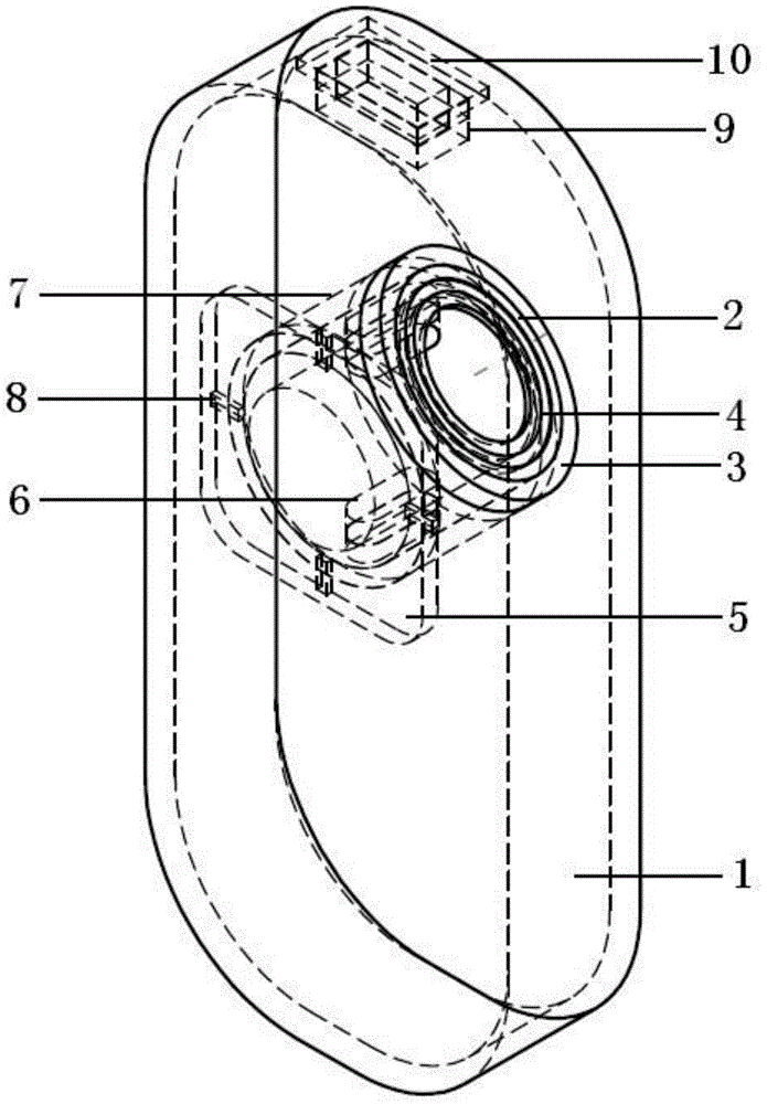
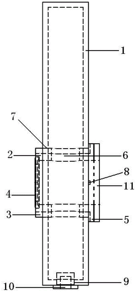
[0027] Such as figure 1 , figure 2 As shown, a bit positioning cooler mentioned in the present invention is characterized in that it includes a water injection box 1 and a conduit 2 for accommodating the drill bit, and the water injection box 1 is provided with a water injection hole 9 in the area above the middle. The water injection hole 9 is provided with a plug 10 that cooperates with the water injection hole 9. The region above the middle of the water injection box 1 is provided with a conduit hole 7 that runs through the front and back of the water injection box 1. The conduit hole 7 and the conduit 2 cooperate with each other. The side of the conduit 2 is provided with a water inlet 6, and one end of the conduit 2 is provided with a fixed piece fixedly connected with the workpiece, and the inner diameter of the conduit 2 at one end of the fixe...


PUM


Abstract

The invention discloses a location cooler of a drill bit. The location cooler comprises a water injection box and a guide pipe, wherein the guide pipe is used for containing the drill bit, a water injection hole is formed in the middle and upper area of the water injection box, a plug which is mutually matched with the water injection hole is arranged in the water injection hole, a guide pipe hole which penetrates through the front part and the rear part of the water injection box is formed in the middle and upper area of the water injection box, the guide pipe hole is mutually matched with the guide pipe, a water inlet hole is formed in the side surface of the guide pipe, one end of the guide pipe is provided with a fixing piece which is fixedly connected with a workpiece, the inner diameter of the guide pipe which is at one end of the fixing piece is greater than the inner diameter of the guide pipe which is at the other end of the fixing piece, and the inner diameter of one end, which is far away from the fixing piece, of the guide pipe is matched with the drill bit. According to the location cooler of the drill bit disclosed by the invention, the drill bit can be used for punching by being arranged in a standing water environment, not only is a better cooling effect obtained, but also water in the water injection box can be repeatedly used, and the utilization rate of water is increased; meanwhile, the location cooler of the drill bit can be adapted to punching on multiple inclined surfaces, the adaptability is very high, and the location cooler of the drill bit is beneficial for increasing the punching efficiency.

Description

technical field [0001] The invention relates to the technical field of drilling positioning cooling devices, in particular to a drill bit positioning cooler. Background technique [0002] In the fields of house decoration, engineering construction and workpiece processing, it is often necessary to drill holes, and drill bits are needed for drilling. A convenient and easy-to-use drill bit positioning cooler is very helpful to improve the efficiency and quality of drilling. The existing Most of the drill bit positioning coolers use water to continuously flow through the drill bit to achieve the purpose of cooling, but the contact area between the water and the drill bit is small in this cooling method, and the cooling effect achieved is not good enough, and the water cannot be recycled. It is very inconvenient to replace the water after completing a hole, which reduces the efficiency of drilling. At the same time, many cooling devices can only be used on vertical or horizontal...

Claims


Application Information

Patent Timeline
Patent Type & Authority Applications(China)
IPC IPC(8): B23Q11/10B23B47/00
CPCB23Q11/10
Inventor 任伟祥
Owner 杭州汉龙金刚石工具有限公司
Why Eureka
Try Eureka