Wire winding machine

A wire winding machine and wire winding slot technology, applied in the field of wire winding machines, can solve the problems of time-consuming and laborious, low efficiency, etc., and achieve the effects of reducing production cost, reducing production time and high production efficiency

Inactive Publication Date: 2015-03-11
GUANGXI LAIBIN YINHAI ALUMINUM PROD
View PDF8 Cites 6 Cited by
  • Summary
  • Abstract
  • Description
  • Claims
  • Application Information

AI Technical Summary

Problems solved by technology

[0002] In the aluminum profile processing industry, small rolls of aluminum wires are used in the oxidation workshop, but the small

Method used


Image

  • Wire winding machine
  • Wire winding machine

Examples


Example Embodiment

[0015] The principles and features of the present invention will be described below with reference to the accompanying drawings. The examples cited are only used to explain the present invention and not used to limit the scope of the present invention.
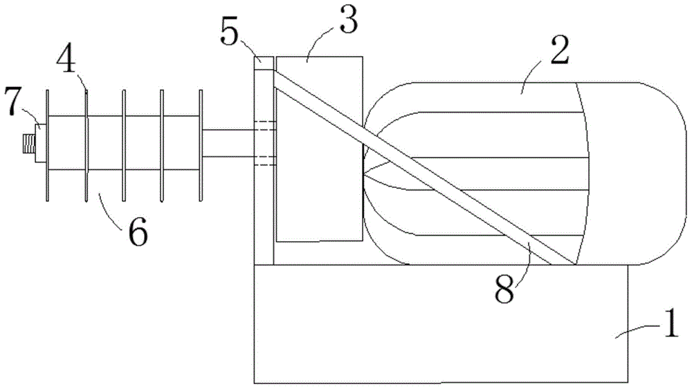
[0016] Such as figure 1 with figure 2 As shown, a winding machine includes a base 1, a motor 2, a reducer 3, and a reel 4. The motor 2 is placed on the upper end of the base 1, and the reducer 3 is placed above the base 1. , And the reducer 3 is connected with the output shaft at the front end of the motor 2, a baffle 5 is provided at the front end of the reducer 3, the baffle 5 is fixedly connected with the base 1, and the reel 4 is provided There are multiple, multiple reels 4 are sleeved in parallel on the output shaft of the front end of the reducer 3, and multiple reels 4 are linked with the output shaft of the front end of the reducer 3, and multiple A plurality of annular winding grooves 6 are formed between the reels 4....


PUM


Abstract

The invention relates to a wire winding machine, which comprises a base, a motor, a speed reducer and a plurality of winding tubes, wherein the motor is arranged at the upper end of the base, the speed reducer is arranged above the base, and is connected with an output shaft arranged at the front end of the motor, the front end of the speed reducer is provided with a baffle plate, the baffle plate is fixedly connected with the base, the winding tubes are parallelly arranged on an output shaft arranged at the front end of the speed reducer in a sleeving way, in addition, the winding tubes are linked with the output shaft arranged at the front end of the speed reducer, and a plurality of wire winding grooves are formed among the winding tubes. Compared with the prior art, the wire winding machine has the advantages that the production time can be reduced, the work intensity can be reduced, and the production efficiency is high.

Description

technical field [0001] The invention relates to a winding machine. Background technique [0002] In the aluminum profile processing industry, small rolls of aluminum wires are used in the oxidation workshop, but the small rolls of aluminum wires have always been manually wound, which is time-consuming and laborious, and the efficiency is extremely low. Contents of the invention [0003] The technical problem to be solved by the present invention is to provide a winding machine capable of reducing production time, reducing work intensity and high production efficiency. [0004] The technical solution of the present invention to solve the above technical problems is as follows: a winding machine, including a base, a motor, a reducer and a reel, the motor is placed on the upper end of the base, and the reducer is placed above the base , and the reducer is connected to the output shaft at the front end of the motor, the front end of the reducer is provided with a baffle plate...

Claims


Application Information

Patent Timeline
IPC IPC(8): B65H54/547B65H67/04
Inventor 何成文陆正新袁贵章黄福林张斌曾志林零长赠
Owner GUANGXI LAIBIN YINHAI ALUMINUM PROD
Why Eureka
Try Eureka