Improved yarn guide frame

An improved technology for the yarn guide frame, which is applied in the direction of conveying filamentous materials, thin material handling, transportation and packaging, etc. It can solve the problems of longitudinal thread tension, low work efficiency, yarn breakage, etc., and prevent over-tightening Stretching, improving work efficiency and reducing frictional resistance

Inactive Publication Date: 2015-03-11
CHANGZHOU HAOFENG LAMPS & LANTERNS FACTORY
View PDF1 Cites 0 Cited by
  • Summary
  • Abstract
  • Description
  • Claims
  • Application Information

AI Technical Summary

Problems solved by technology

[0002] The yarn guide frame is used to realize the yarn guide function in the spinning field. It predetermines a trajectory for the yarn. The existing yarn guide frame settings are mostly vertical and horizontal parallel to each other, so that the yarn trajectory The direction changes too much, which makes the longitudinal line prone to tension and knotting during movement
And Chinese patent (CN201512629U) discloses a kind of yarn guide frame, in use, because the friction of installation bottom plate often can make yarn break, affects production, and a yarn guide frame can only guide one yarn, and work efficiency is relatively high. Low

Method used


Image

  • Improved yarn guide frame
  • Improved yarn guide frame

Examples


Embodiment Construction

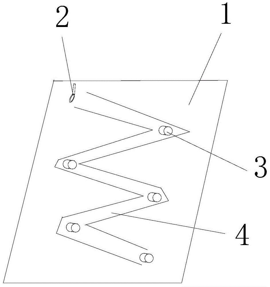
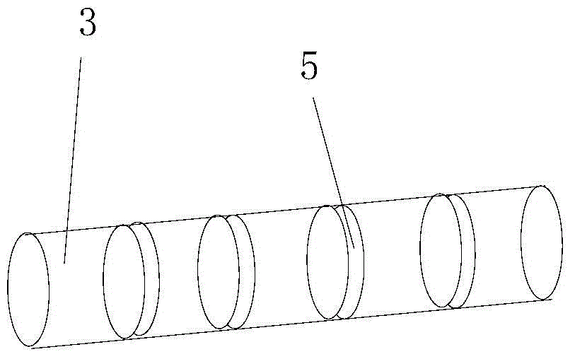
[0015] Such as figure 1 , figure 2 An improved yarn guide frame shown includes an installation base plate 1, the installation base plate 1 is equipped with guide wire hooks 2 and guide wire rods 3, and the described guide wire hooks 2 are located on the upper part of the installation base plate 1, and several Guide wire rod 3, the described installation base plate 1 is provided with guide groove 4, and described guide groove 4 is provided with rubber layer, and described guide wire rod 3 is installed in guide groove 4 and compresses described rubber layer. Described guide wire rod 3 is five. The guide grooves 4 are distributed in a broken line. The guide wire rod 3 is arranged at the turning point of the guide groove 4 . A limiting groove 5 is arranged on the guide wire rod 3 .

[0016] The invention has a simple structure, can prevent the yarn from changing direction when it moves, and prevent the yarn from being too tight, so that the distance between the guide wire ho...


PUM


Abstract

The invention discloses an improved yarn guide frame. The improved yarn guide frame comprises a mounting bottom plate, wherein the mounting bottom plate is provided with a silk guide hook and silk guide rods; the silk guide hook is positioned on the upper part of the mounting bottom plate; a plurality of silk guide rods are arranged below the silk guide hook; the mounting bottom plate is provided with a guide groove; a rubber layer is arranged in the guide groove; the silk guide rods are arranged in the guide groove and press the rubber layer. Larger turn is not produced during movement of a yarn to prevent the yarn from being over-tightened, so that the distance between the silk guide hook and the silk guide rods is relatively small, and the yarn passing through the silk guide hook is quickly and effectively guided. During tightening of a yarn, since the yarn is in direct contact with the rubber layer in the guide groove, the friction resistance is reduced; the yarn guided by the guide groove on the silk guide rods is not in direct contact with the mounting bottom plate, so that the problem of yarn breakage is further prevented, and the working efficiency is improved.

Description

technical field [0001] The invention relates to the field of spinning equipment, in particular to an improved yarn guide frame. Background technique [0002] The yarn guide frame is used to realize the yarn guide function in the spinning field. It predetermines a trajectory for the yarn. The existing yarn guide frame settings are mostly vertical and horizontal parallel to each other, so that the yarn trajectory The direction change is too large, which makes the longitudinal line prone to tension and knotting during movement. And Chinese patent (CN201512629U) discloses a kind of yarn guide frame, in use, because the friction of installation bottom plate often can make yarn break, affects production, and a yarn guide frame can only guide one yarn, and work efficiency is relatively high. Low. Contents of the invention [0003] In order to overcome the above-mentioned technical problems, the present invention provides an improved yarn guide frame, which can completely solve ...

Claims


Application Information

Patent Timeline
IPC IPC(8): B65H57/02B65H57/04
Inventor 蔡浩平
Owner CHANGZHOU HAOFENG LAMPS & LANTERNS FACTORY
Why Eureka
Try Eureka