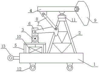
Improved oil field pumping unit

A technology for pumping units and oil fields, which is applied in the fields of exploitation fluid, wellbore/well parts, earthwork drilling and production, etc. It can solve the problem of high price of double-speed motors and frequency converters, the motor pulley cannot be too small, and cannot meet the requirements of low stroke times and other issues to achieve the effect of high work efficiency, low cost and simple structure

Inactive Publication Date: 2015-03-11
CHENGDU JUZHI IND DESIGN
View PDF6 Cites 2 Cited by
  • Summary
  • Abstract
  • Description
  • Claims
  • Application Information

AI Technical Summary

Problems solved by technology

The existing low-stroke adjustment method is generally to reduce the diameter of the motor pulley and increase the reduction ratio, but the motor pulley should not be too small, otherwise it will not be able to transmit normally.
Therefore, reducing the number of strokes by reducing

Method used


Image

  • Improved oil field pumping unit

Examples


Example Embodiment

[0013] See figure 1 An improved oilfield pumping unit shown includes a base 1, a support frame 2, a driving device 3, and a beam 4. The support frame 2 is mounted on the base 1, and the beam 4 is mounted on the support frame 2. The base 1 is provided with a frame 5, the drive device 3 is mounted on the frame 5, the output end of the drive device 3 is connected with a gearbox 6, and the output end of the gearbox 6 is connected with a crank rod 7, The front end of the crank rod 7 is hinged with a connecting rod 8, one end of the connecting rod 8 is hinged on the cross beam 4, the front end of the cross beam 4 is provided with a donkey head 9, the base 1 is provided with a reserve power supply 10, so The reserve power source 10 is connected to the driving device 3.

[0014] A shock absorber 11 is provided at the connection between the beam 4 and the support frame 2, and the donkey head 9 is detachably connected to the beam 4.

[0015] The bottom of the base 1 is provided with walkin...


PUM


Abstract

The invention discloses an improved oil field pumping unit. The improved oil field pumping unit comprises a base, a support frame, a driving device and a crossbeam, wherein the support frame is arranged on the base; the crossbeam is arranged on the support frame; a frame is arranged on the base; the driving device is arranged on the frame; the output end of the driving device is connected with a gearbox; the output end of the gearbox is connected with a crank rod; a connecting rod is hinged to the front end of the crank rod; one end of the connecting rod is hinged to the crossbeam; the front end of the crossbeam is provided with a horse head; the base is provided with a back-up power supply; the back-up power supply is connected with the driving device. The improved oil field pumping unit is simple in structure, convenient to use and mount, simple in operation, low in cost, high in work efficiency, low in energy consumption, conveniently moved, wide in application range and long in service life, and has safe and reliable effects.

Description

technical field [0001] The invention relates to an improved oil field pumping unit. Background technique [0002] At present, the improved oil pumping units are mostly used in oil production in oil fields. In order to improve the mechanical efficiency, the pumps are often produced with long stroke and low stroke parameters. , so that the down of the sucker rod is synchronized with the operation of the pumping unit. The existing low-stroke adjustment method is generally to reduce the diameter of the motor pulley and increase the reduction ratio, but the motor pulley should not be too small, otherwise it will not be able to transmit normally. Therefore, reducing the number of strokes by adjusting the pulley is limited, and cannot meet the requirements of low stroke times. Sometimes a frequency converter or a two-speed motor is used to adjust the stroke frequency on site to make the stroke frequency of the pumping unit reach the required stroke frequency. Difficult to promot...

Claims


Application Information

Patent Timeline
IPC IPC(8): E21B43/00
CPCE21B43/00
Inventor 文国栋
Owner CHENGDU JUZHI IND DESIGN
Why Eureka
Try Eureka