Disc cam type double-acting mud pump

A mud pump, double-acting technology, which is applied to the components of the pumping device for elastic fluid, pumps, piston pumps, etc. The effect of wearing parts life, reducing maintenance times and maintenance time, and reducing maintenance costs

Active Publication Date: 2020-11-06
XIAN RES INST OF CHINA COAL TECH& ENG GROUP CORP
View PDF10 Cites 2 Cited by
  • Summary
  • Abstract
  • Description
  • Claims
  • Application Information

AI Technical Summary

Problems solved by technology

[0003] The three-cylinder reciprocating mud pump that is widely used now generally transmits power through the crankshaft to make the piston push the medium to increase the pressure so as to achieve the purpose of conveying the medium. The action mode of this structural form of the mud pump can only be unidirectional. The mechanical efficiency is low and the flow pulse is large. When a large pump volume is required, limited by the number of cylinders and the single-acting mode, the effect of increasing the pump volume can only be achieved by increasing the stroke times of the mud pump.
The high-stroke movement will cause great working pressure on the vulnerable parts of the mud pump, such as the mud pump piston, piston cylinder liner and pump head assembly, and reduce the life of the vulnerable parts. According to statistics, 80% of the failure modes of the mud pump are Caused by severe piston wear and poor sealing performance, this failure mode is inseparable from the high-stroke movement of the mud pump. At the same time, the cylinder liner and piston of the mud pump are not only made of special materials, but also have complicated manufacturing processes and expensive prices, and the replacement time is long. , affecting the progress of drilling operations and seriously affecting the progress of the project

Method used


Image

  • Disc cam type double-acting mud pump
  • Disc cam type double-acting mud pump
  • Disc cam type double-acting mud pump

Examples


Embodiment 1

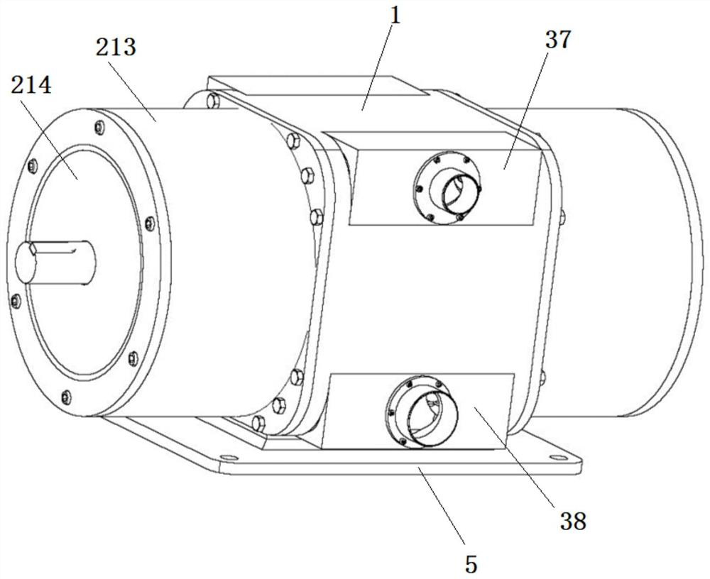
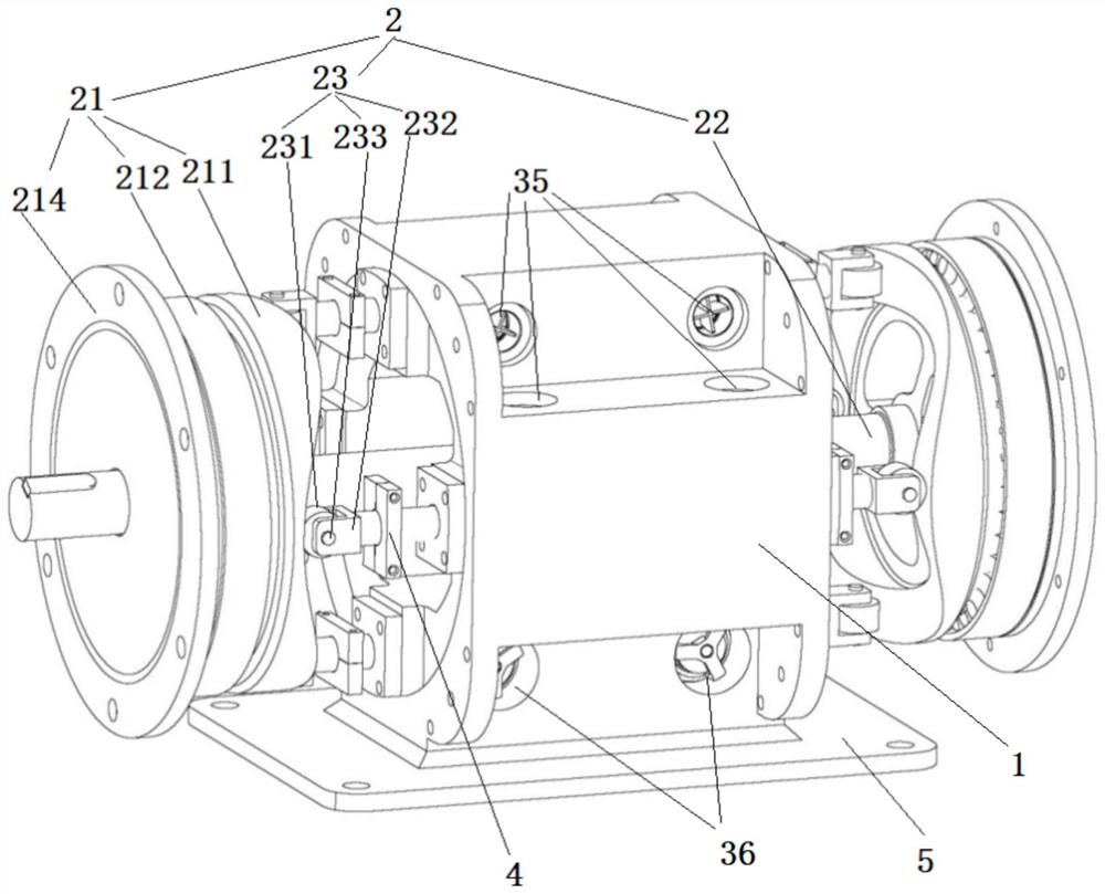
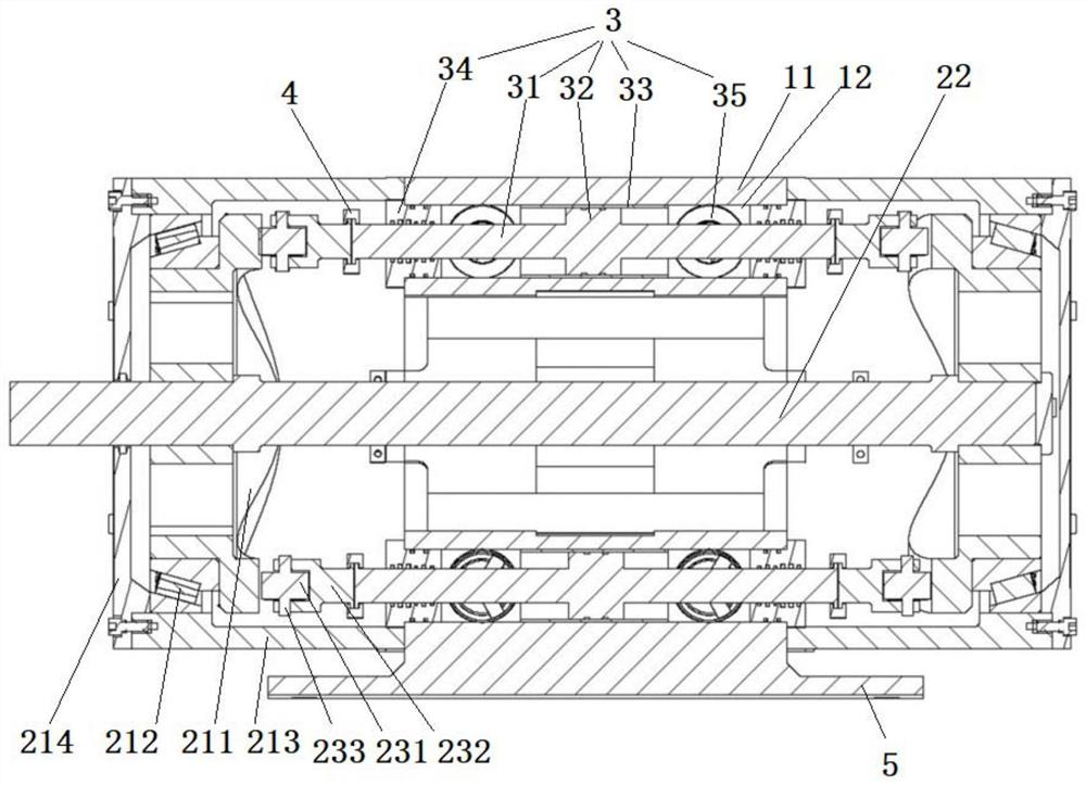
[0047] Such as Figure 1 to Figure 3As shown, this embodiment provides a disc cam type double-acting mud pump, which includes a mud pump casing 1 , a power end assembly 2 and a fluid end assembly 3 .

[0048] The power end assembly 2 includes disc cam mechanisms 21 arranged on both sides of the mud pump casing, a power connection shaft 22 connecting the two disc cam mechanisms, and a plurality of driving mechanisms 23 with roller links.

[0049] The disc cam mechanism 21 comprises: a disc cam 211, a bearing 212, a side case 213 and a side case cover 214 arranged at the end of the side case 213, which are arranged coaxially from the inside to the outside; one side of the disc cam 211 is Alternating crests and troughs, the curved surfaces of the two disc cams 211 on the side of the mud pump casing 1 are opposite and misplaced so that the crests of one disc cam 211 correspond to the troughs of the other disc cam 211 to ensure that the two disc cams 211 The axial distance between...


PUM


Abstract

The invention discloses a disc cam type double-acting mud pump which comprises a mud pump box body, a power end assembly and a hydraulic end assembly. The power end assembly comprises a disc cam mechanism, a power connecting shaft for connecting the two disc cam mechanisms and a plurality of connecting rod driving mechanisms with rollers. The hydraulic end assembly comprises a piston rod, a piston, a piston cylinder liner and end face sealing covers arranged at the two ends of the piston cylinder; the side walls of cavities on the two sides of the piston are each provided with a suction high-pressure valve and a discharge high-pressure valve; the two ends of the piston rod are connected with roller frames, and the rollers fluctuate on the curved surface when disc cams rotate, so that the piston rod can axially reciprocate between the two disc cams; when the piston moves in one direction in the piston cylinder, a valve element of the discharge high-pressure valve in the cavity, toward the moving direction, of the piston cavity is opened to output media, and a valve element of the suction high-pressure valve in the other cavity is opened to suck in media. Single-cylinder double action can be realized, and the effects of low stroke frequency, short stroke and large displacement can be realized.

Description

technical field [0001] The invention belongs to the technical field of mud pumps, in particular to a disc cam type double-acting mud pump. Background technique [0002] The mud pump is the "heart" of the drilling operation. The mud pump provides power for the drilling flushing medium, so that the flushing medium can complete the tasks of driving the screw drilling tool, carrying cuttings, cooling and lubricating the drilling tool, etc., which is to ensure the directional drilling efficiency and hole formation rate. The key components are widely used in oilfield operations and coalfield geological exploration. [0003] The three-cylinder reciprocating mud pump that is widely used now generally transmits power through the crankshaft to make the piston push the medium to increase the pressure so as to achieve the purpose of conveying the medium. The action mode of this structural form of the mud pump can only be unidirectional. The mechanical efficiency is low and the flow pul...

Claims


Application Information

Patent Timeline
Patent Type & Authority Applications(China)
IPC IPC(8): F04B15/02F04B9/04F04B53/10F04B53/16
CPCF04B15/02F04B9/042F04B53/10F04B53/162
Inventor 田宏杰田东庄董萌萌荣明达米陇峰周春李鹏温国栋
Owner XIAN RES INST OF CHINA COAL TECH& ENG GROUP CORP
Why Eureka
Try Eureka