Piston type two-stroke fan

A piston type, two-stroke technology, used in piston pumps, liquid variable capacity machinery, mechanical equipment, etc., can solve problems such as poor adjustment accuracy, difficult to meet modern industrial production and services, and serious negative effects.

Pending Publication Date: 2019-06-28
吴平安
View PDF0 Cites 2 Cited by
  • Summary
  • Abstract
  • Description
  • Claims
  • Application Information

AI Technical Summary

Problems solved by technology

This backward adjustment method not only wastes precious energy, but also has poor adjustment accuracy, which makes it difficult to meet the requirements of modern industrial production and service, and has serious negative effects.

Method used


Image

  • Piston type two-stroke fan
  • Piston type two-stroke fan
  • Piston type two-stroke fan

Examples


Embodiment Construction

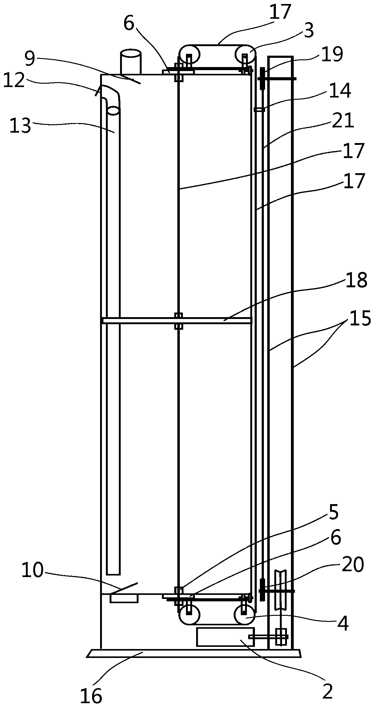
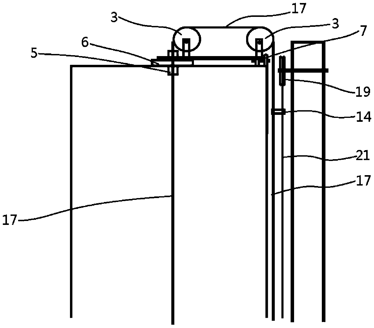
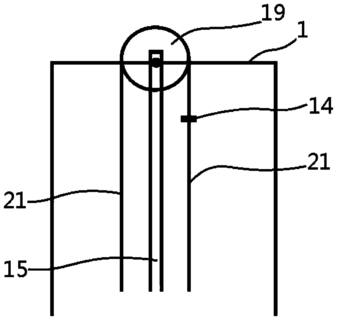
[0025] As shown in the figure; a piston-type two-stroke fan according to the present invention is characterized in that the two-stroke fan consists of a two-stroke fan cylinder 1, a speed regulating motor 2, an upper double pulley 3, a lower double pulley 4, a hollow bolt 5, Thrust bearing 6, upper roller 7, lower roller 8, upper one-way air inlet valve 9, lower one-way air inlet valve 10, upper one-way air outlet valve 11, lower one-way air outlet valve 12, lower one-way air outlet pipe 13. An annular rope 17, a piston wind plate 18, an upper sprocket 19, a lower sprocket 20, a chain 21, a rotating shaft telescopic buckle 14, and a bracket 15; wherein the speed regulating motor 2 is arranged on the base 16; wherein the hollow There are two bolts 5, which are located at the center point of the top plate and the bottom plate of the double-stroke fan 1; one of the hollow bolts 5 passes through the center hole of the thrust bearing 6 to fix the upper double pulley 3, and the other...


PUM


Abstract

The invention discloses a piston type two-stroke fan, and relates to the technical field of air blowers. According to the specific technical scheme, the two-stroke fan is composed of a two-stroke fanair cylinder, a speed adjustment motor, upper dual pulleys, lower dual pulleys, hollow bolts, thrust bearings, an upper rolling wheel, a lower rolling wheel, an upper one-way air inlet valve, a lowerone-way air inlet valve, an upper one-way air outlet valve, a lower one-way air outlet valve, a lower one-way air outlet pipe, an annular rope, a piston type air plate, an upper chain wheel, a lower chain wheel, a chain, a rotating shaft telescopic buckle and a support. The piston type two-stroke fan has the advantages that the two-stroke fan is long in stroke, low in stroke frequency, large in cylinder diameter, large in blast capacity, high in air pressure and low in noise and is suitable for multiple scenes achieving spaced air blowing.

Description

technical field [0001] The invention relates to a blower, in particular to a piston type two-stroke blower. Background technique [0002] At present, centrifugal blowers are used in most occasions. The working principle of centrifugal blowers is similar to that of centrifugal fans, except that the air compression process is usually carried out by several working impellers (or several stages) under the action of centrifugal force. The blower has a high-speed rotating rotor. The blades on the rotor drive the air to move at high speed. The centrifugal force makes the air flow in the involute-shaped casing along the involute to the fan outlet. The high-speed airflow has a certain wind pressure. Fresh air enters through the center of the casing to replenish it. [0003] It is particularly worth mentioning that most fans have the phenomenon of large horses and small carts during use, and due to changes in production and technology, it is necessary to frequently adjust the flow, p...

Claims


Application Information

Patent Timeline
Patent Type & Authority Applications(China)
IPC IPC(8): F04B35/04F04B39/12
Inventor 吴平安
Owner 吴平安
Why Eureka
Try Eureka