Hydraulic sand jet perforation choke manifold

A throttling manifold and hydraulic jet technology, applied in the production fluid, wellbore/well components, sealing/packing, etc., can solve problems such as gate valve erosion damage, inability to accurately control casing pressure, etc. corrosion, improve perforation efficiency, and facilitate replacement

Active Publication Date: 2015-03-11
BC P INC CHINA NAT PETROLEUM CORP +1
View PDF9 Cites 7 Cited by
  • Summary
  • Abstract
  • Description
  • Claims
  • Application Information

AI Technical Summary

Problems solved by technology

[0006] The purpose of the present invention is: in order to solve the problem that the existing choke manifold cannot accurately control the casing pressure during hydraulic sandblasting and perforating, and the gate valve is seriously damaged due to the erosion of the sand-carrying fluid, the present invention provides a controllable casing A special choke manifold for hydraulic sandblasting perforation with high pressure, improved perforation efficiency and corrosion resistance

Method used


Image

  • Hydraulic sand jet perforation choke manifold

Examples


Embodiment 1

[0019] Since the existing choke manifold cannot accurately control the casing pressure during hydraulic sandblasting perforation, and the gate valve is severely damaged by the erosion of the sand-carrying fluid, in order to overcome the above problems, the embodiment provides a hydraulic sandblasting Special choke manifold for perforation.

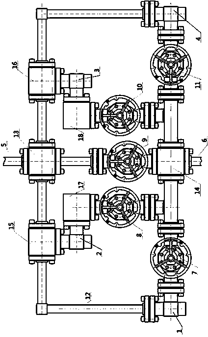
[0020] Such as figure 1 As shown, a hydraulic sandblasting and perforating throttling manifold includes a first four-way pipe 13 and a second four-way pipe 14. The first slab gate valve 7, the third slab gate valve 9 and the fifth slab gate valve 11 are arranged side by side between them; the first slab gate valve 7 and the fifth slab gate valve 11 are located on both sides of the third slab gate valve 9.

[0021] A first fixed throttle valve 1 is provided between the end of the first flat gate valve 7 connected to the first pipeline cross 13; the end of the fifth flat gate valve 11 connected to the first pipeline cross 13 A fourth fixed...

Embodiment 2

[0029] On the basis of embodiment 1, the application mode of the present invention is:

[0030] (1), first connect the manifold inlet 5 with the wellhead casing gate valve;

[0031] (2), open the first flat gate valve 7, the second flat gate valve 8, the fourth flat gate valve 10, the fifth flat gate valve 11, and close the third flat gate valve 9;

[0032] (3) Test the throttling pressure, perform tubing pumping according to the perforation displacement requirements, and test the casing pressure. If the casing pressure is lower than the design pressure, close the first flat gate valve 7, the second flat gate valve 8, and the second flat gate valve as required. Any one or more of the four slab gate valves 10 and the fifth slab gate valve 11 until the casing pressure reaches the design requirement.

[0033] (4) If the casing pressure is greater than the design pressure, stop pumping, and replace any of the first flat gate valve 7, the second flat gate valve 8, the fourth flat ...


PUM


Abstract

The invention discloses a hydraulic sand jet perforation choke manifold. The hydraulic sand jet perforation choke manifold comprises a first pipeline cross and a second pipeline cross, and a first flat gate valve, a third flat gate valve and a fifth flat gate valve are arranged between the first pipeline cross and second pipeline cross in parallel; the first flat gate valve and the fifth flat gate valve are located at two sides of the third flat gate valve; a first fixed throttle valve is arranged between the first flat gate valve and one horizontal end of the first pipeline cross, and a fourth fixed throttle valve is arranged between the fifth flat gate valve and the other horizontal end of the first pipeline cross. The hydraulic sand jet perforation choke manifold is capable of precisely controlling the casing pressure in the hydraulic sand jet perforation process so as to avoid the pipeline crack due to over-high pressure or the stratum sand spray or perforation tool failure due to low pressure, the fixed throttle valves are good in erosion wearing resistance and convenient to change, the cost is saved, and the working efficiency is improved.

Description

technical field [0001] The invention relates to a throttling manifold for hydraulic sandblasting and perforating. Background technique [0002] Choke manifold is a control device used to adjust wellbore pressure during oil drilling. It is a pipeline network connected by various valves, pipes and pipe joints, including three-way, four-way and five-way. It is placed in oil and gas wells. side of the wellhead. At present, in the choke manifold used in the drilling industry, the control of the choke valve and parallel gate valve is mainly manual and hydraulic, and the choke branch is relatively simple. The gate valve is used to control the pressure in the well and the flow direction of the fluid. The above-mentioned control operation is completely performed manually, which is not only cumbersome, labor-intensive, and poor in safety, but also the accuracy of manual control is not easy to grasp, resulting in poor pressure stability in the well. [0003] With the increase of dee...

Claims


Application Information

Patent Timeline
Patent Type & Authority Applications(China)
IPC IPC(8): E21B43/114E21B34/02
CPCE21B34/02E21B43/114
Inventor 兰建平杨红斌费节高李绪宜端木晓亮潘耀瑞佘亚军张清龙陈雄徐俊芳
Owner BC P INC CHINA NAT PETROLEUM CORP
Why Eureka
Try Eureka