Crankshaft front-end structure of diesel engine

A crankshaft front end, diesel engine technology, applied in mechanical equipment, engine components, machines/engines, etc., can solve the problems affecting the overall layout of the engine front end, small torque, incompatibility, etc., to achieve high power, large transmission torque, and compact assembly structure Effect

Inactive Publication Date: 2015-03-11
GUANGXI YUCHAI MASCH CO LTD
View PDF8 Cites 7 Cited by
  • Summary
  • Abstract
  • Description
  • Claims
  • Application Information

AI Technical Summary

Problems solved by technology

[0003] Among them, when the crankshaft pulley is installed on the front end of the crankshaft with an interference fit, the torque transmitted by it is small. In order to ensure the requirement of large torque transmission by the crankshaft pulley, the diameter of the front end of the crankshaft needs to be increased, which will affect the overall layout of the front end of the engine. To meet the increasing pressure of engine cost and the tight layout space of the whole machine, the diesel engine needs to be designed into a more compact structure.
[0004] When the crankshaft pulley is installed on the front end of the crankshaft by bolts, the diameter of the front end of the crankshaft (crankshaft small head) also needs to be increased, which will also affect the overall layout of the front end of the engine, and cannot adapt to the increasing pressure of engine cost and the layout space of the whole machine. Under tight conditions, diesel engines need to be designed into a more compact structure

Method used


Image

  • Crankshaft front-end structure of diesel engine
  • Crankshaft front-end structure of diesel engine
  • Crankshaft front-end structure of diesel engine

Examples


Embodiment Construction

[0021] The specific embodiments of the present invention will be described in detail below in conjunction with the accompanying drawings, but it should be understood that the protection scope of the present invention is not limited by the specific embodiments.

[0022] Unless expressly stated otherwise, throughout the specification and claims, the term "comprise" or variations thereof such as "includes" or "includes" and the like will be understood to include the stated elements or constituents, and not Other elements or other components are not excluded.

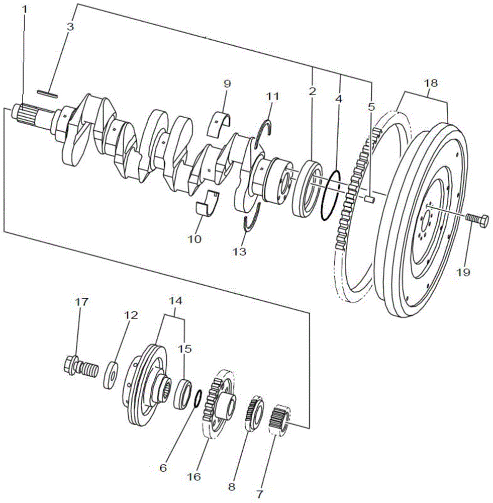
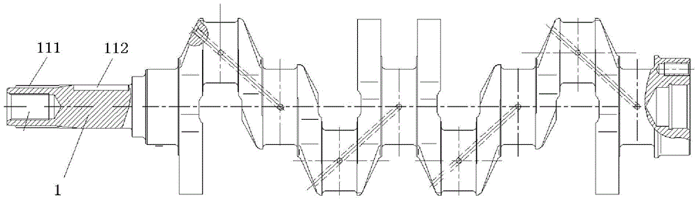
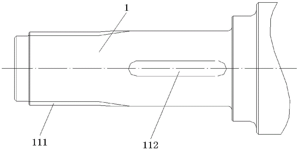
[0023] like figure 1 As shown, the specific structure of the crankshaft front end structure of a diesel engine according to a specific embodiment of the present invention includes: a crankshaft front end (crankshaft small head) 1, and a crank pulley 14, a balance shaft drive gear 16, and a crankshaft timing gear 7 installed on the crankshaft front end. And oil pump drive gear 8. Wherein, crankshaft pulley 14 and crankshaf...


PUM


Abstract

The invention discloses a crankshaft front-end structure of a diesel engine. The crankshaft front-end structure of the diesel engine comprises a crankshaft front end, a crankshaft belt pulley, a balance shaft drive gear, a crankshaft timing gear and an oil pump drive gear, wherein the crankshaft front end is positioned at one end of a crankshaft; an external spline is formed in the outer side of the outer circumferential surface of the crankshaft front end; a first flat key groove which extends axially is formed in the inner side of the outer circumferential surface of the crankshaft front end and is used for arranging a flat key; an internal spline which is matched with the external spline of the crankshaft front end to form spline connection is formed in the inner circumferential surface of a central shaft hole of the crankshaft belt pulley; a second flat key groove which is in flat key connection with the flat key of the crankshaft front end is formed in the inner circumferential surface of the central shaft hole of each of the balance shaft drive gear, the crankshaft timing gear and the oil pump drive gear. According to the crankshaft front-end structure of the diesel engine, the crankshaft belt pulley is connected with the crankshaft front end through the spline, so that the assembling structure is compact; the transfer torque of the crankshaft front end is large; the power of a drive accessory is high.

Description

technical field [0001] The invention relates to the field of engines, in particular to a front end structure of a crankshaft of a diesel engine. Background technique [0002] In existing diesel engines, the crankshaft pulley in the front end mechanism of the crankshaft usually adopts an interference fit or is mounted on the front end of the crankshaft (crankshaft small end) by bolts. [0003] Among them, when the crankshaft pulley is installed on the front end of the crankshaft with an interference fit, the torque transmitted by it is small. In order to ensure the requirement of large torque transmission by the crankshaft pulley, the diameter of the front end of the crankshaft needs to be increased, which will affect the overall layout of the front end of the engine. To meet the increasing pressure of engine cost and the tight layout space of the whole machine, the diesel engine needs to be designed into a more compact structure. [0004] When the crankshaft pulley is insta...

Claims


Application Information

Patent Timeline
Patent Type & Authority Applications(China)
IPC IPC(8): F02F11/00
CPCF02B67/06F02B2275/06
Inventor 覃星念黄第云苏怀林
Owner GUANGXI YUCHAI MASCH CO LTD
Why Eureka
Try Eureka