Optical lens

An optical lens and lens technology, applied in the field of optical lenses, to achieve the effect of reducing the optical length and diameter, reducing the distance, and reducing the diameter

Active Publication Date: 2015-03-11
NINGBO SUNNY AUTOMOTIVE OPTECH
View PDF5 Cites 16 Cited by
  • Summary
  • Abstract
  • Description
  • Claims
  • Application Information

AI Technical Summary

Problems solved by technology

[0003] The existing vehicle front-view lens cannot meet the requirements of miniaturization under the condition of small distortion and high pixel

Method used


Image

  • Optical lens
  • Optical lens
  • Optical lens

Examples


Embodiment 1

[0021] Embodiment 1 of the present invention provides an optical lens. The optical lens includes in order from the object side to the image side: a front lens group, a diaphragm, a rear lens group, a color filter and an imaging surface.

[0022] The front lens group is a first lens with positive refractive power; the rear lens group includes in sequence from the object side to the image side: a second lens with negative refractive power, a third lens with positive refractive power, The fourth lens and the fifth lens, the fourth lens and the fifth lens form a cemented lens, and the rear lens group has positive refractive power.

[0023] The optical length TTL of the optical lens and the entire group focal length value F of the optical lens satisfy TTL / F≤2.3;

[0024] The shape of the first lens is a meniscus shape, and the shape of the second lens is a biconcave shape.

[0025] The optical length TTL of the optical lens refers to the distance from the outermost point on the o...

Embodiment 2

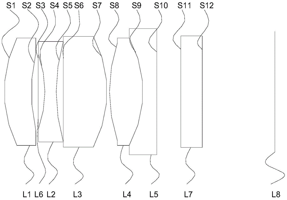
[0045] see Figure 1a , is a schematic structural diagram of an optical lens provided in Embodiment 2 of the present invention. The optical lens includes in sequence from the object side to the image side: a front lens group, a diaphragm L6, a rear lens group, a color filter L7 and an imaging surface L8.

[0046] The front lens group is the first lens L1 with positive refractive power; the rear lens group includes in sequence from the object side to the image side: the second lens L2 with negative refractive power, the third lens L2 with positive refractive power The lens L3, the fourth lens L4, and the fifth lens L5, the fourth lens L4 and the fifth lens L5 form a cemented lens, and the rear lens group has positive refractive power.

[0047] Such as Figure 1aAs shown, specifically, the shape of the first lens L1 is a meniscus shape, the shape of the second lens L2 is a biconcave shape, correspondingly, the shape of the fourth lens L4 is a biconvex shape, and the shape of the...

Embodiment 3

[0063] see Figure 2a , is a schematic structural diagram of an optical lens provided in Embodiment 3 of the present invention. The optical lens includes in sequence from the object side to the image side: a front lens group, a diaphragm L6, a rear lens group, a color filter L7 and an imaging surface L8.

[0064] The difference between the present embodiment and the second embodiment lies in that the structure of the cemented lens in the optical lens of the present embodiment is different. Specifically, the shape of the fourth lens L4 is a meniscus shape, and the shape of the fifth lens L5 is a biconvex shape.

[0065] As a modification of this embodiment, the shape of the fourth lens L4 may also be a biconcave shape.

[0066] Starting from the object side, the surfaces of each element are numbered in sequence. The first lens L1 includes mirror S1 and mirror S2, the diaphragm surface of diaphragm L6 is S3, the second lens L2 includes mirror S4 and mirror S5, and the third le...


PUM


Abstract

The invention provides an optical lens. The optical lens sequentially comprises a first lens, a diaphragm and a rear lens group from an object space to an image space, wherein the first lens has positive focal power and is of a crescent shape; the rear lens group has positive focal power; the group comprises a second lens, a third lens, a fourth lens and a fifth lens; the second lens has negative focal power and is of a double concave shape; the third lens has positive focal power; the fourth lens and the fifth lens are combined to form a balsaming lens; the ratio of the optical length of the optical lens to the whole group of focal length values is not greater than 2.3. Light is collected and converged from a large angle by the first lens with the positive focal power and the crescent shape, so that the caliber of the second lens is reduced; the light emitted by the first lens is diverged by the second lens with the negative focal power and the double concave shape, so that the caliber of the third lens is reduced and the distance between the second lens and the third lens is reduced on the premise that the imaging requirement is met; the light emitted by the second lens is converged by the third lens with the positive focal power, so that the caliber of the balsaming lens is reduced, further the optical length and the caliber of the optical lens are reduced, and the miniaturization is realized.

Description

technical field [0001] Embodiments of the present invention relate to the technical field of optical imaging, and in particular, to an optical lens. Background technique [0002] With the development of active safety in the automotive industry, the requirements for vehicle front-view cameras continue to increase. On the premise of keeping lens distortion small and megapixels, due to the limitation of lens assembly space, it is required that the total length of the lens should be as short as possible, so as to meet the requirements of lens miniaturization. [0003] The existing vehicle front-view lens cannot meet the requirements of miniaturization under the condition of small distortion and high pixel. Contents of the invention [0004] An embodiment of the present invention provides an optical lens to achieve miniaturization while maintaining small distortion and high pixels. [0005] An embodiment of the present invention provides an optical lens, which sequentially in...

Claims


Application Information

Patent Timeline
Patent Type & Authority Applications(China)
IPC IPC(8): G02B13/00G02B13/06
CPCG02B13/0015G02B13/06
Inventor 姚波张野谢前森
Owner NINGBO SUNNY AUTOMOTIVE OPTECH
Why Eureka
Try Eureka