Welded structure for vehicle body panel

A technology for welding structures and body panels, applied in the welding of straight seams, superstructures, welding equipment, etc., can solve the problems of reduced peel strength and widening of the welded part, and can prevent the reduction of production efficiency, improve welding speed, The effect of improving production efficiency

Active Publication Date: 2015-03-11
HONDA MOTOR CO LTD
View PDF5 Cites 8 Cited by
  • Summary
  • Abstract
  • Description
  • Claims
  • Application Information

AI Technical Summary

Problems solved by technology

However, in doing so, not only the man-hours required for seam welding are doubled, but also the width of the joining flange becomes wider because two parallel we...

Method used


Image

  • Welded structure for vehicle body panel
  • Welded structure for vehicle body panel
  • Welded structure for vehicle body panel

Examples


no. 1 approach

[0064] first embodiment

[0065] First, according to Figure 8 ~ Figure 10 The welding structure of this embodiment will be described.

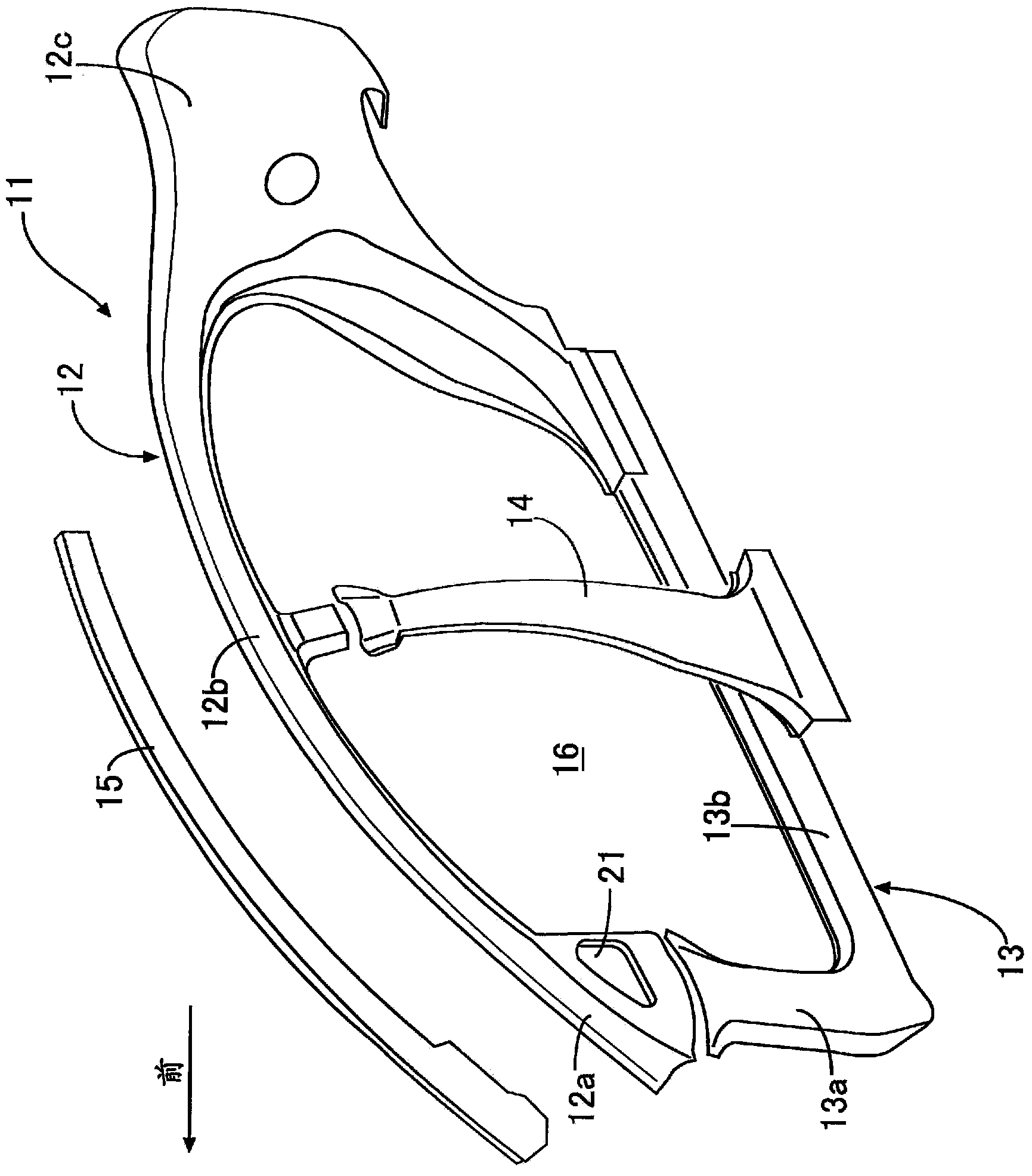
[0066] This embodiment is suitable for joining the first panel 41, the second panel 42, and the third panel 43 by welding. The first panel 41 having a hat-shaped cross-section has a pair of first joining flanges 41a, 41a, the second panel 42 having a hat-shaped cross-section has a pair of second joint flanges 42a, 42a along the two side edges, and the third panel 43 having a hat-shaped cross-section has a pair of third joint flanges along the two side edges 43a, 43a.

[0067] The second panel 42 and the third panel 43 are arranged in a row in the longitudinal direction, and in a state where their opposite ends overlap each other, a second panel is superimposed on the first joining flanges 41a, 41a of the first panel 41 . The second joint flanges 42 a , 42 a of the panel 42 and the third joint flanges 43 a , 43 a of the third panel 43 . Th...

no. 2 approach

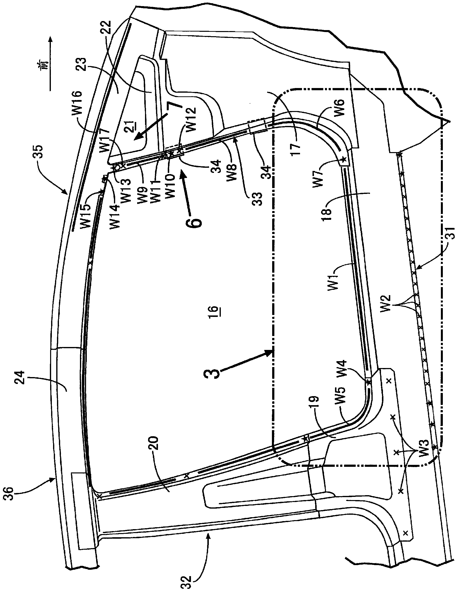
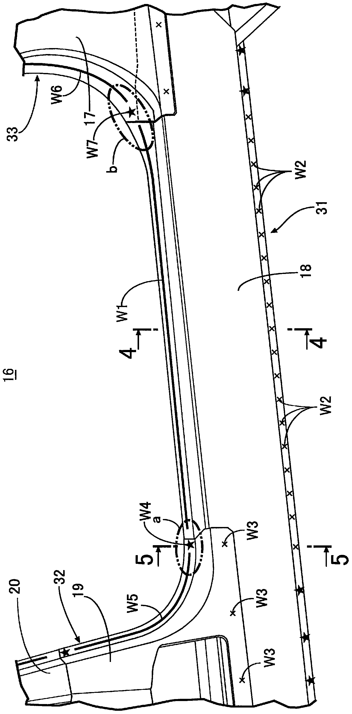
[0095] exist Figure 9 In the illustrated first embodiment, the flange widths of the first to third joining flanges 41a to 43a of the first to third members 41 to 43 are constant in the longitudinal direction, but in the Figure 11 In the shown second embodiment, the flange widths of the first to third joint flanges 41a to 43a are wider in the triple-layered portion and narrower in the double-layered portion.

[0096] Thus, the flange width required for spot welding Wb with a large nugget diameter d and seam welding Wa with a small nugget width w can be ensured, while preventing unnecessary increase in the flange width and contributing to lightening weight.


PUM


Abstract

A second joint flange (42a) formed along an edge of a second panel (42) and a third joint flange (43a) formed along an edge of a third panel (43) are each superposed on a first joint flange (41a) formed along an edge of a first panel (41), a portion in which the first joint flange (41a) and the second joint flange (42a) are superposed in two layers, and a portion in which the first joint flange (41a) and the third joint flange (43a) are superposed in two layers are subjected to seam welding (Wa), and a portion in which the first joint flange (41a), the second joint flange (42a) and the third joint flange (43a) are superposed in three layers is subjected to spot welding (Wb). The welding speed is increased by subjecting the two-layered portion with a long weld length to seam welding (Wa), and peel strength can be increased by subjecting, to spot welding (Wb), the three-layered portion that is difficult to subject to seam welding (Wa) and easy to peel off because the number of superposed layers is large.

Description

technical field [0001] The present invention relates to a welding structure of a vehicle body panel in which joining flanges formed along edges of the vehicle body panel are overlapped and joined by welding. Background technique [0002] For example, as described in the following Patent Document 1, seam welding is conventionally known in which the surfaces of superimposed steel plates are clamped and pressed by a pair of roller electrodes, and the two roller electrodes are pressed along the steel plates while supplying current to the two roller electrodes. The surface of the roller is rolled, thereby performing continuous welding by melting the steel plate sandwiched between the two roller electrodes by Joule heat. [0003] In addition, the following patent document 2 describes laser welding in which when two closed cross-sections are formed by disposing a reinforcing member between an outer member and an inner member, two welding lines are used to join two flanges of the ou...

Claims


Application Information

Patent Timeline
IPC IPC(8): B62D25/02B23K11/00B23K11/06B62D25/04B62D25/06B62D25/20
CPCB23K2201/006B23K11/061B62D25/02B62D25/025B62D27/02B23K2101/006B23K11/06B23K11/087B23K11/10B23K11/11B62D25/04B62D25/06B62D25/08
Inventor 山田孝行古崎雄也
Owner HONDA MOTOR CO LTD
Why Eureka
Try Eureka