Device and method for handling drill string components in rock drilling and rock drill rig

A control device and drill string technology, which is applied to drilling equipment and methods, drill pipes, rotary drilling rigs, etc., can solve the problems of operator lifting and clamping injuries, people's pressure, etc., and achieve great control advantages and good performance. The Effects of Drilling Economics

Active Publication Date: 2015-03-11
安百拓有限公司
View PDF10 Cites 3 Cited by
  • Summary
  • Abstract
  • Description
  • Claims
  • Application Information

AI Technical Summary

Problems solved by technology

These work steps are stressful and pose a non-negligible risk of lifting and pinching injuries to the operator

Method used


Image

  • Device and method for handling drill string components in rock drilling and rock drill rig
  • Device and method for handling drill string components in rock drilling and rock drill rig
  • Device and method for handling drill string components in rock drilling and rock drill rig

Examples


Embodiment Construction

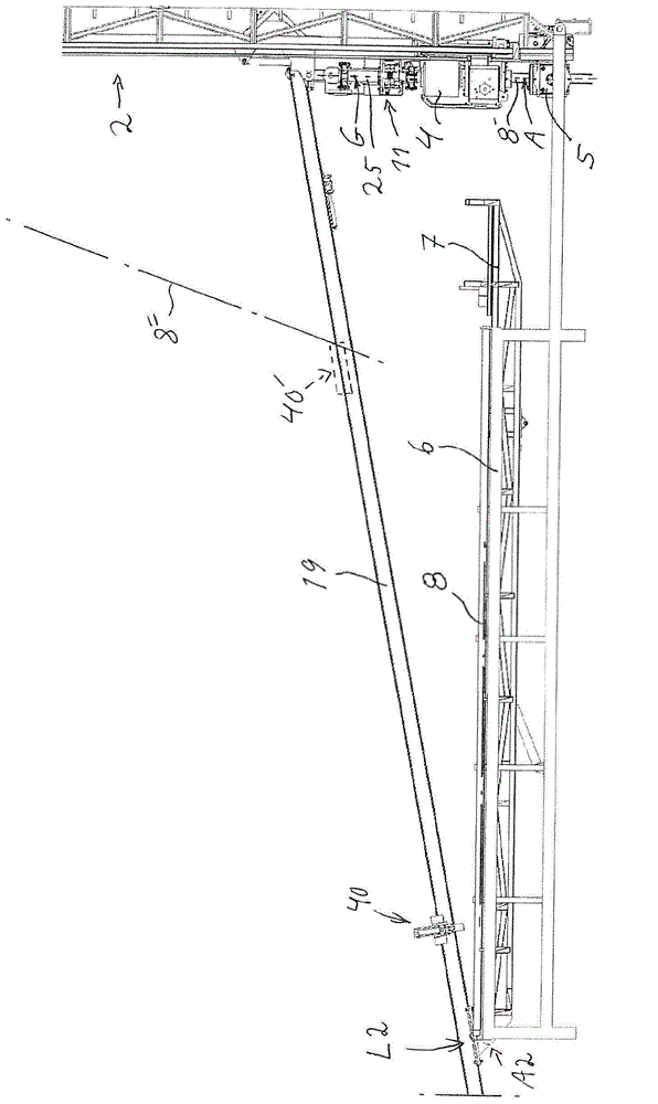
[0040] figure 1 Shown is a feed beam 2 of a rock drilling machine for core drilling that can be adjusted to different angles. The drilling rig comprises a rotary device 4 which is supported on the feed beam 2 to move back and forth. Below (in the figure) the rotating device 4 is provided a pipe holder 5 for temporarily holding a drill string when necessary.

[0041] Beside the feeding beam 2, a power drive kit (not shown) and a drawworks (not shown) for supplying pressurized fluid and the like to the rock drilling machine are arranged. The charging rack 6 is arranged to receive drill string components (indicated by broken line 8) which are respectively entered into and removed from the rock drilling machine in the manner described below.

[0042] Charging rack 6 can be constituted in various ways, but in figure 1 Illustrated in the form of a generally horizontal table, the clamping member 6 can be tilted so that the drill string component 8 can be rolled towards the swing a...


PUM


Abstract

A handling device for handling drill with a gripper shuttle (40) which is drivingly displaceable along a guiding beam (19) being fastenable to the drill rig in order to extend in a direction from the feed beam while forming an angle therewith, wherein the gripper shuttle (40) has a pivotally arranged guiding gripper (41) for in a first position in a first outermost position on the guiding beam grip a first end portion of a drill string component (8), being intended for lifting from a position outside the rig, the other end portion of which being intended to be in threaded engagement with a lifting plug or the like for co-operation with said lifting winch, and wherein the gripper shuttle (40) in a second position in a second inner position on the guiding beam adjacent to the feed beam (2) is arranged with the guiding gripper (41) to line up said gripped drill string component in the region of the drill string position.

Description

technical field [0001] The invention relates to a handling device for manipulating drill string components relative to a drilling rig comprising a feed beam on which a feed swivel is displaceably supported and a drawworks for lifting to be threaded A first drill string component to a second drill string component at a drill string location of the drilling rig. The invention also relates to a corresponding method and a rock drilling machine equipped with such an actuation device. Background technique [0002] Core drilling for exploration is usually performed by rock drilling rigs, wherein drill string components are placed in active drill string positions, raised or lowered in the borehole by means of winches. The noose is secured to the uppermost drill string component by means of hangers. Since core drilling is used to extract drilled core for study, tubular drill string components are used. During lifting of the drill string, which is often performed to change the dril...

Claims


Application Information

Patent Timeline
Patent Type & Authority Applications(China)
IPC IPC(8): E21B19/15
CPCE21B19/15E21B19/155E21B3/022E21B3/025
Inventor 里卡德·古斯塔夫松
Owner 安百拓有限公司
Why Eureka
Try Eureka