Electric brake device

A technology of electric braking and electric motor, applied in the direction of braking transmission device, braking action starting device, brake, etc., can solve problems such as controllability deterioration, and achieve the effect of improving controllability and accuracy

Active Publication Date: 2015-03-18
HONDA MOTOR CO LTD
View PDF13 Cites 9 Cited by
  • Summary
  • Abstract
  • Description
  • Claims
  • Application Information

AI Technical Summary

Problems solved by technology

When the torque (resultant torque) in a certain direction is amplified and the sensor mounting advance angle of the mounting position of the above-mentioned angle sensor is excessively set, there is a problem that the controllability in the opposite direction of rotation deteriorates.

Method used


Image

  • Electric brake device
  • Electric brake device
  • Electric brake device

Examples


Embodiment approach

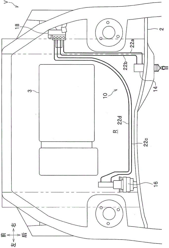
[0076] figure 1 It is a figure which shows the arrangement|positioning structure of the electric brake device of an embodiment of this invention on a vehicle. in figure 1 The arrows in the middle indicate the front, rear, left, and right directions of the vehicle V. The electric brake device 10 is installed so as to be mountable in various vehicles including, for example, a motor vehicle driven only by an engine (internal combustion engine), a hybrid vehicle, an electric vehicle, and a fuel cell vehicle.

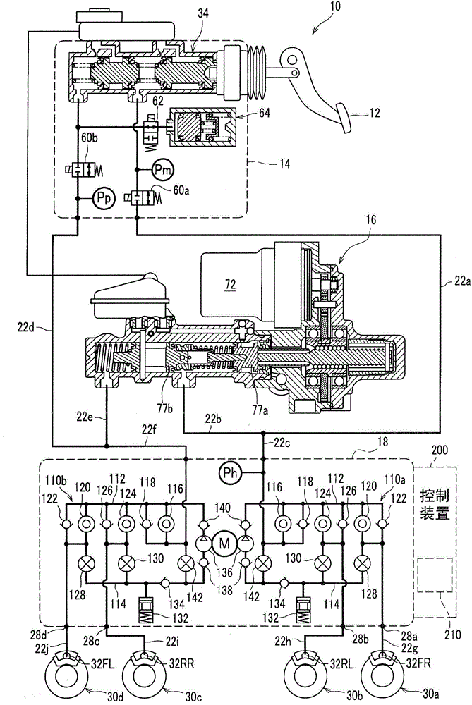
[0077] The electric brake device 10 provided with the vehicle stability assist device 18 (hereinafter referred to as the VSA device 18, VSA is a registered trademark) of the present embodiment has a By Wire brake system and a conventional hydraulic brake The system is composed of both of these systems. The brake-by-wire system is used for normal use to transmit electric signals to operate the brakes, and the hydraulic brake system is used for fail-safe conditions to transmit hy...


PUM


Abstract

An electric brake device includes: a motor cylinder device that generates a hydraulic pressure in accordance with a brake operation of a driver with an electric motor; a rotational angle sensor that detects a rotor rotational angle θ of the electric motor; and a motor control section that controls an output torque of the electric motor corresponding to the rotor rotational angle θ and controls the electric motor by advancing a detection value of the rotational angle sensor. The current phase setup section sets a current phase to an advanced side as an electrical advance control. The current phase setup section inhibits the advancing the detection value when the electric motor performs reversed rotation, or sets the current phase to a retarded side.

Description

Technical field [0001] The present invention relates to an electric braking device that can be applied to a wire-controlled braking system. Background technique [0002] The By Wire type electric brake system uses driver input such as pedal stroke to calculate the target brake pressure, and generates hydraulic pressure through various actuators to achieve the target hydraulic pressure. [0003] In an electric brake system, an electric motor is used as an actuator that generates brake hydraulic pressure. This electric motor sometimes uses an IPM (Interior Permanent Magnet) motor in which a permanent magnet is arranged on a rotor and the coil is driven by an inverter (for example, refer to Patent Document 1). In addition to the magnet torque caused by the attractive / repulsive force of the coil and the permanent magnet, the IPM motor can also obtain the reluctance torque generated by the change in the magnetic resistance of the gap between the stator and the rotor. Therefore, the IP...

Claims


Application Information

Patent Timeline
Patent Type & Authority Applications(China)
IPC IPC(8): B60T8/17B60T13/138B60T13/66H02P6/06H02P6/08H02P6/28
CPCB60T7/042B60T13/662B60T13/745B60T13/146B60T8/4081
Inventor 岛田贵史木寺和治植浦总一郎
Owner HONDA MOTOR CO LTD
Why Eureka
Try Eureka