
Transparent vacuum pipeline

A vacuum pipeline and transparent technology, applied in the direction of roads, tracks, tunnel systems, etc., can solve the problems of economic loss of railway transport operators, difficult welding and construction, short replacement cycle, etc., to avoid engineering losses in hoisting, disassembly and replacement. The effect of reducing economic losses and reducing maintenance costs

Active Publication Date: 2015-03-18
DALIAN WHIM SCI & TECH LTD CO
View PDF6 Cites 50 Cited by
  • Summary
  • Abstract
  • Description
  • Claims
  • Application Information

AI Technical Summary

Problems solved by technology

[0004] A difficult problem will be encountered in the operation of vacuum pipelines: the current maintenance method that people think of for the construction of vacuum pipelines is to shut down the whole or part of the high-speed railway line, and lift the vacuum pipeline as a whole for replacement and maintenance, which will make the whole line The line is in a state of suspension, which will bring difficulties to high-speed railway traffic and bring certain economic losses to railway transport operators. This is more serious and long-lasting than the short-term delay of aircraft due to weather.
[0005] Another difficulty will be encountered in the operation of vacuum pipelines: limited by the performance and life of current materials, pipelines should not be made of transparent materials. This is because: although glass materials are transparent and airtight, they are brittle, hard and easy to crack, and are not easy to weld and construct ; Although the transparent resin material has good toughness and is easy to construct, it has poor aging resistance and the replacement cycle is shorter than glass. Frequent replacement of materials will increase the number of outages of the entire line. Therefore, steel plates or reinforced concrete with sealing films will be considered. Mixed sealing technology is used to make pipes, so that the pipes are light-tight. In the train, only the black pipes can be seen but the beautiful scenery outside the high-speed train cannot be seen, and it feels like a fly in the ointment

Method used


Image

  • Transparent vacuum pipeline
  • Transparent vacuum pipeline

Examples


Embodiment Construction

[0035] The present invention will now be described in further detail in conjunction with the accompanying drawings.

[0036] Now, a single-channel vacuum pipeline is used as an example to illustrate the technical points of the present invention.

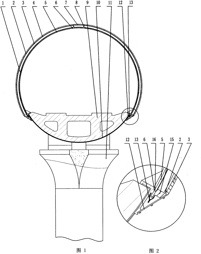
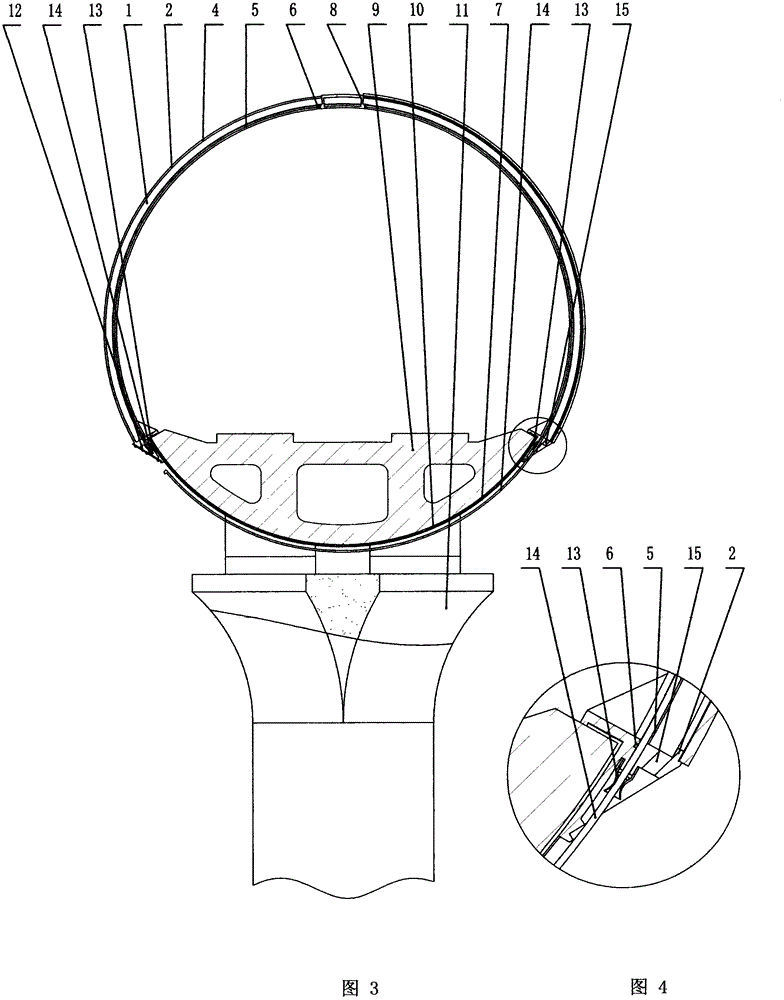
[0037] like figure 1 As shown, the bottom of the vacuum duct includes a rail foundation 9 , which is wrapped with a foundation sealing plate 10 to seal the rail foundation 9 . The vacuum pipeline usually adopts an elevated structure and is supported by the support column 11 .

[0038] The track foundation 9 of the present invention is provided with a support frame 1 , both sides of the support frame 1 are arc-shaped, the whole is arch-shaped, and supported on both sides of the base sealing plate 10 . The outer layer of the support frame 1 is provided with an outer support rib plate 2, the outer part of the outer support rib plate 2 is tightly connected to the pipeline sealing plate 3, and the outer supporting rib plate 2 and the pi...


PUM


Abstract

The invention provides a transparent vacuum pipeline which is characterized by consisting of a pipeline framework and a transparent sealing plate, wherein the pipeline framework is provided with an inner-layer sealing supporting ribbed plate and is provided with a technical sealing plate insertion slot. when in need of maintenance, a technical sealing plate is inserted between the inner-layer sealing supporting ribbed plate and an outer-layer pipeline, so that the whole easy-to-break outer-layer pipeline cannot leak in replacement and maintenance processes, and normal passing of trains in the pipeline cannot be affected; non-stop maintenance is realized, the phenomenon that the whole high-speed railway stops running due to damage to the pipeline or maintenance of the pipeline is avoided, energy for vacuumizing at each time is saved, and a vacuum pipeline high-speed railway technology is more energy-saving.

Description

Technical field [0001] The invention relates to the technical field of vacuum pipeline engineering construction, in particular to a vacuum pipeline ultra-high-speed maglev train system, especially a non-stop maintenance technology for transparent vacuum pipelines. Background technique [0002] The high-speed transportation technology of vacuum pipelines has attracted widespread attention due to its aircraft-like speed and remarkable energy-saving advantages, and it is also an inevitable trend in the development of high-speed railways. [0003] At present, people's confused understanding of vacuum pipelines and the negative effects brought about by them make the high-speed transportation technology of vacuum pipelines questioned. Because some experts and scholars use advanced orbital technology that is too difficult and unrealistically high pursuit of speed, people think that the high-speed transportation technology of vacuum pipelines is more difficult than landing on the mo...

Claims


Application Information

Patent Timeline
Patent Type & Authority Applications(China)
IPC IPC(8): B61B13/10
CPCB61B13/10
Inventor 刘忠臣
Owner DALIAN WHIM SCI & TECH LTD CO
Learn More